
Abstrak
Suatu studi eksperimental telah dilakukan untuk meneliti pengaruh dimensi bukaan pada perilaku balok tinggi-T hybrid beton bertulang yang dikenai torsi murni. Empat balok diuji dibawah beban torsi murni, dimana tiga balok mempunyai dimensi bukaan yang berbeda dan satu balok tanpa bukaan sebagai tolok ukur. Program pengujian dan hasil-hasilnya disajikan dalam makalah ini. Hasil pengujian memperlihatkan bahwa dimensi bukaan dengan diameter lebih dari 100 mm secara signifikan mengurangi kekuatan torsi pada saat retak dan saat maksimum. Hasil eksperimental juga menunjukkan bahwa sudut kemiringan retak terhadap sumbu memanjang balok meningkat dengan meningkatnya dimensi bukaan.
Kata-kata kunci: Balok tinggi-T hybrid beton bertulang, dimensi bukaan, pola retak, torsi retak, torsi maksimum, sudut puntir.
1. Introduction
In order to save headroom, an opening in a beam is often required for ducting services. According to ACI Building Code (1999), beams with span/depth ratio of about five or less and loaded at the top or on it's compression face are categorized as deep beams. Deep beams with transverse opening are rarely subjected to pure torsion, normally the loading will be a combination of bending, shear and torsion. However, it is beneficial a this stage to have an investigation under pure torsion first, as a basis for attempting to understand their complex behavior under combined loadings (Alwis and Mansur, 1987).
In a region with high risk of earthquakes, reducing the mass of buildings is in general an alternative choice for minimizing the earthquake effects on the building structures. It could be achieved by substituting heavier normal weight concrete of floors with light weight concrete. In practice, generally slab are cast on the top of beams. Therefore, it is reasonable to take into account the T-shaped section of such beams in their capacity evaluations. The same ACI Building Code (1999) also mentioned that flanged sections may be taken into account in determining the torsional strength of the beams.
Research on torsional behavior of shallow beams was extensively conducted since several decades ago.
1) Research Student, Civil Engineering Department of ITB
2) Professor of Civil Engineering, Civil Engineering Department of ITB
3) Professor of Civil Engineering, Civil Engineering Department of ITB
4) Lecturer, Civil Engineering Department of ITB
However, research on the torsional behavior of deep beams has received little attention (Akhtaruzzaman and Hasnat, 1989). As a result, current codes such as ACI Building Code (1999) as well as CEB-FIP Model Code (1993) do not have any provision for deep beams subjected to torsional loads. Investigations on the torsional behavior of deep beams were reported by Akhtaruzzaman and Hasnat (1989); Samman (1995) and Samman et al. (1996). However, their investigation were addressed to beams of plain concrete with purely rectangular cross section. Therefore, investigation on the torsional behavior of deep T-beams is still needed.
Preliminary research to investigate the effect of hybrid sections on the torsional behavior of reinforced concrete deep T-beams with opening was carried out by Lisantono et al. (2001). This research was later continued to investigate the effect of web opening locations, in horizontal as well as in vertical direction, on the torsional behavior of reinforced concrete deep T-beam. (Lisantono et al. 2002a, 2002b). To obtain a clear understanding on the effect of web opening dimension on the torsional behavior of reinforced concrete hybrid deep T-beams, experimental investigations were recently carried out in the Laboratory of Structures and Materials of ITB.
2. Experimental Program
2.1 Specimen detail
Four beam specimens were tested under pure torsion. The first beam (B4HS) was reinforced concrete hybrid deep T-beam without opening, cast of normal weight concrete web and light weight concrete flanges. The second, third and fourth beams (B4HOD1; B4HO and
B4HOD3) were reinforced concrete hybrid deep Tbeams with web opening diameters of 100 mm; 200 mm and 300 mm respectively. The circular openings were located at mid span and mid depth of the beam. All specimens have the same span of 2000 mm and the same nominal cross-sectional dimensions. Details of the specimens are shown in Figure 1.
Longitudinal and transverse reinforcements were kept constant for all beams. To force failure to occur in the zone of interest, heavy reinforcements were provided at the ends of the beam. The zone of interest was selected to be 1550 mm to allow for at least two complete spiral crack propagations to occur along the beam and to fit the specimen into the test-rig of the laboratory (see Figure 2).
2.2 Materials properties
The reinforcements of the beam were 4 D13 mm and 4 φ10 mm longitudinal bars having an average yield strength of 350 MPa, and φ6 mm closed stirrups having an average yield strength of 260 MPa. Spacing of stirrups was kept constant along the beam at 150 mm. The tested beams were cast of two kinds of concrete material. The beams had light weight concrete (LWC) flanges and normal weight concrete (NWC) webs. Locally available crushed aggregates with maximum size of 19 mm were used for NWC, while pelletized expanded clay aggregates with maximum size of 12 mm were utilized for LWC. The first and the third beams were cast out of batches different from those of the second and the fourth beams. However the mechanical properties of the produced concretes have shown no significant difference due to the careful exercise of mixing. The mix design and mechanical properties of the concrete is shown in Table 1.
Table 1. The properties of concretes
| Specimen | B4HS & B4HO | B4HOD1 & B4HOD3 | ||
|---|---|---|---|---|
| Concrete | NWC | LWC | NWC | LWC |
| Density ( kg/m3 ) | 2356.96 | 1721.98 | 2374.20 | 1780.65 |
| fc' ( MPa ) | 35.40 | 40.74 | 35.68 | 40.03 |
| fsp ( MPa ) | 3.32 | 2.79 | 3.41 | 2.76 |
| Ec ( GPa ) | 25.15 | 14.70 | 26.04 | 15.57 |
| µ (Poisson ratio) | 0.18-0.22 | 0.18-0.26 | 0.19-0.26 | 0.19-0.23 |
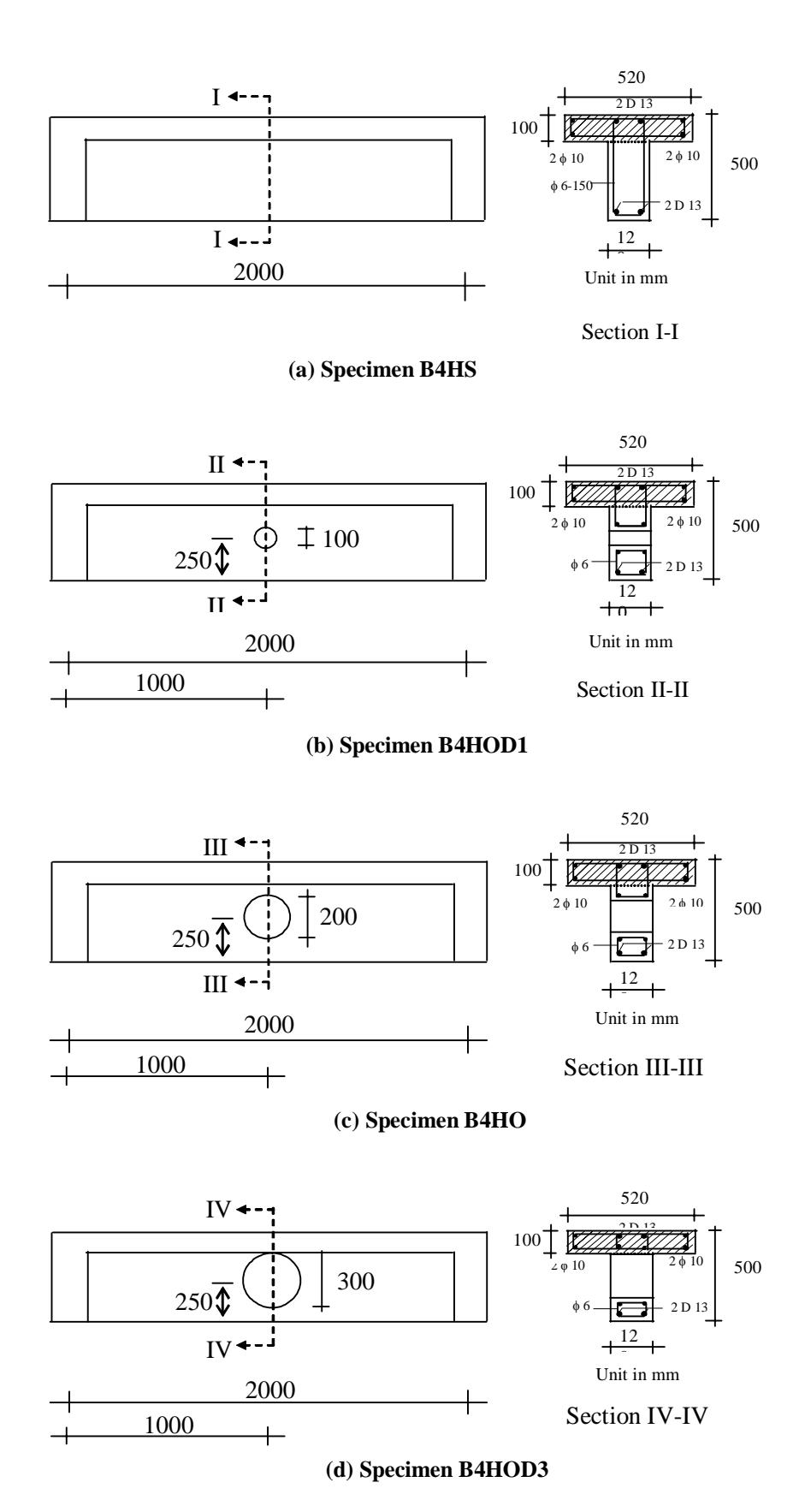
Figure 1. Details of specimens
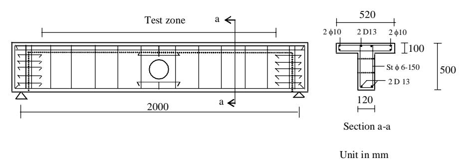
Figure 2. Test zone and reinforcement arrangement of the beam
2.3 Test setup and instrumentation
The loading arrangement and test setup are illustrated in Figure 3. A 120 kN hydraulic actuator was utilized to apply the load at the West support. The load had an 850 mm arm from the centroidal axis of the beam. A reaction arm was used at the East support to balance the applied load by attaching the arm to the laboratory test floor. The East support was restrained from twisting, while the West support was free to rotate to provide the required applied torque force. The West support was designed to properly provide the necessary twist with respect to the centroidal axis of the beam.
he specimens were instrumented for measurements of prevailing deflections and rotations. The deflection and rotation due to the torque force were measured using LVDT and inclinometers respectively. Electrical resistance strain gages were used to measure strains in the reinforcements and concrete.
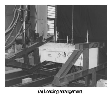
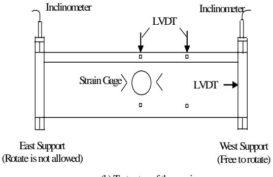
(b) Test setup of the specimen
Figure 3. Loading arrangement and test setup of the specimen
2.4 Test specimen
The beams were first whitewashed and then square grid of 50 mm were drawn for easy identification of crack patterns. All beams were tested under monotonic loading, using displacement controlled loading at a rate of 0.02 mm/sec until the ultimate torque was reached, after which the rate was increased to 0.05 mm/sec until beam failure took place. Measured data of loads, deformations and strains were read through a computer driven data acquisition system. The crack propagation was marked to obtain the crack pattern of the beams.
3 Test Results and Discussions
3.1 Crack pattern
The crack patterns viewed from the side of the specimens B4HS, B4HOD1, B4HO, and B4HOD3 are shown in Figure 4.
The initial crack of specimen B4HS appeared on the North Face near the West support, starting at mid depth of the beam and propagated up and down in the diagonal direction at an angle of approximately 45 degrees with respect to the axis of the beam. Before continuing from the web into the flange, the crack propagated along the corner line of the web-flange interface for approximately 100-150 mm. The number of cracks parallel to the initial crack subsequently increased as the applied torque is increased, eventually forming complete spirals until the maximum twist was reached.
The first crack of specimens B4HOD1, B4HO, and B4HOD3 appeared on the North and South face, initiated at the lower right hand corner of the opening and continued to the upper left hand corner of the opening. This crack propagated upward and downward in the diagonal direction as the applied torque increases. The angle of crack inclination of specimen B4HOD1, B4HO, and B4HOD3 were approximately 45 deg, 50 deg, and 55 deg respectively. The crack propagated to the flange, and like in the case of B4HS, continued along the corner line of web-flange interface for a short distance of about 100-150 mm. More cracks parallel to the initial crack appeared as the applied torque increases which eventually made complete spirals of
(a) Crack pattern of specimen B4HS
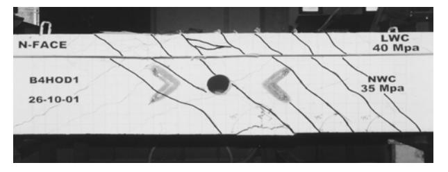
(b) Crack pattern of specimen B4HOD1
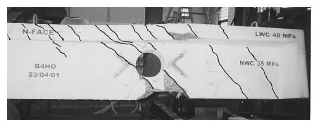
(c) Crack pattern of specimen B4HO
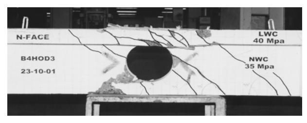
(d) Crack pattern of specimen B4HOD3
Figure 4. The crack pattern of the tested specimens
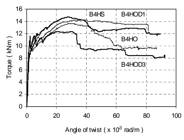
Figure 5. Torque-twist curve of the tested beams
3.2 Strength characteristics
The torque-twist curve of the tested beams is presented in Figure 5. It shows that generally the strength characteristics of the tested beams up to first cracking behave essentially linear. After first cracking, preceded by a small drop in torque, the curves increased nonlinearly with increasing twist up to their ultimate torque. It was observed that the small drop in torque occurred when the crack propagated a short distance along the corner line of the web-flange interface. After reaching their ultimate torque, the curves decreased non-linearly with increasing twist, and proceeded with a section of an approximately horizontal plateau, indicating a state of yielding prior to collapse. It was also observed that in the regime of non-linear curves, the number of cracks parallel to the initial crack increased as the twist increases, forming complete spirals of cracks until the maximum twist was reached. This phenomenon indicates that there was a redistribution of internal stresses to form a truss action where reinforcement acted as tension links between the concrete compressive struts.
3.3 Torque strength and angle of twist
The experimental results of torque strength as well as angle of twist of the tested beams at cracking and at the ultimate stage can be seen in Table 2. Taking the ratios of the cracking and the ultimate torque of specimen B4HOD1 over those of B4HS results into values of 0.984 and 0.969 respectively. The small differences of less than 4 percent, indicate that the opening with 100 mm diameter does not affect the cracking torque as well as the ultimate torque of the beam. The ratios of the cracking torque of B4HO and B4HOD3 over that of B4HS were found to be 0.805 and 0.769 respectively. For the case of the ultimate torque, those rational values were 0.929 and 0.838 respectively. It can be seen that the opening of 200 mm diameter decreased the cracking and the ultimate torque by 19.524 and 7.056 percent respectively, while the opening diameter of 300 mm decreased those torques by 23.016 and 16.194 percent respectively. It can be seen also that the twist angle at ultimate strength of specimen B4HOD3 has dropped by 23.856 percent of that of specimen B4HS, indicating that the stiffness of the beam decreases rapidly when the opening diameter become large. These results show that an opening diameter greater than 0.2h will significantly affect the torsional behavior of the deep T-beam, where h is the depth of the beam.
3.4 Reinforcement strains
Figure 6 and Figure 7 show the strains of web stirrup and longitudinal bar respectively of the specimen
| Table 2. The torque strength and twist angle of the tested specimens |
|---|
| Beam | At cracking | At ultimate | ||
|---|---|---|---|---|
| Torque (kNm) | Twist ( x 10-3 rad/m) | Torque (kNm) | Twist ( x 10-3 rad/m) | |
| B4HS | 10.710 | 1.989 | 14.697 | 28.152 |
| B4HOD1 | 10.540 | 1.926 | 14.246 | 32.301 |
| B4HO | 8.619 | 2.147 | 13.660 | 29.226 |
| B4HOD3 | 8.245 | 1.702 | 12.317 | 21.436 |
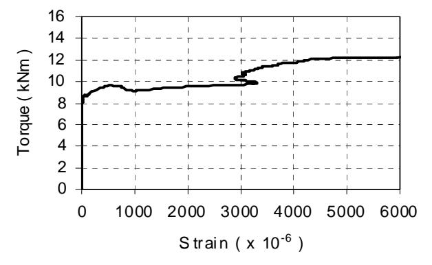
Figure 6. Stirrup strains of B4HO
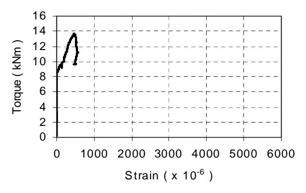
Figure 7. Longitudinal bar strains of B4HO
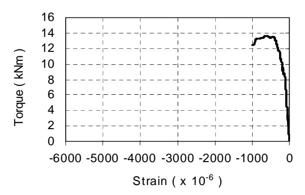
Figure 8. Surface concrete compressive strains of B4HO
B4HO at section 850 mm from East support. The figures indicate that the reinforcement bars seem to have no effect on the torsional capacity of the beam before first cracking of concrete, so it can be said that at the linear regime the torque was mainly resisted by the concrete. This is obvious since significant strain in reinforcement bars only start immediately after the cracking of concrete. These strains continue to grow well into the yield regime of the bars together with the growth of crack widths.
3.5 Concrete surface strain
The compression strains of surface concrete of specimen B4HO at section 850 mm from East support are shown in Figure 8. The curve indicates that the compressive stresses in concrete initiated at low torque loads, then continued to increase beyond the cracking torque. The large stirrup tensile strains apparently contributed significantly to the large ductilities of the beams.
4. Conclusion
Based on the obtained experimental results, the following conclusions can be drawn :
- 1. The torsional behavior of reinforced concrete hybrid deep T-beam with web opening are essentially linear before cracking, after which the torque increased non-linearly with increasing twist. Upon reaching their ultimate strengths the torque in the beams decreased non-linearly and concluded with a yield condition prior to collapse.
- 2. The torque before cracking of concrete was mainly resisted by concrete. After cracking the compression concrete together with the large stirrups tensile strains contributed to the large ductility of the beam.
- 3. The opening dimension with diameters larger than 0.2h, where h is the depth of the beam, significantly affect the deterioration of the angle of twist, the cracking and the ultimate torques of the beam.
5. Acknowledgment
The research work reported herein was made possible due to funding from the Competitive Research Grant of the Directorate General of Higher Education under contract No.46/P2IPT/DPPM/PHBL/III/2003. The authors gratefully acknowledge this support. The authors also thank the Laboratory of Structures and Materials, Civil Engineering Department of ITB, and the Laboratory of Structural Mechanics of the Inter University Research Center of ITB for the use of their research facilities.