
Abstrak
Faktor aksi kelompok diteliti dalam studi eksperimental ini. Plywood dengan tebal 18 mm digunakan sebagai pelat penyambung sisi dan kayu utama terbuat dari meranti (shorea sp.) dan sengon (paraserianthes falcataria). Korelasi antara faktor aksi kelompok dengan jumlah paku dalam satu baris diteliti dari pengujian dengan beban tekan uni-aksial dengan variasi satu sampai dengan sepuluh buah paku. Sambungan dengan 3 baris majemuk dengan 3, 6, dan 9 paku dalam satu baris juga diuji dengan uji beban tekan dan tarik uni-aksial. Faktor aksi kelompok yang dikorelasikan dengan jumlah paku untuk satu baris didapat dari analisa regresi. Persamaanpersamaan regresi yang disajikan adalah faktor aksi kelompok pada batas proporsional (Cgp), faktor aksi kelompok pada 5% offset diameter (Cg5%) dan faktor aksi kelompok pada batas ultimit (Cgu). Kekuatan sambungan pada 5% offset diameter mendekati kekuatan sambungan dari harga disain berdasarkan draft Peraturan Kayu Indonesia 2000. Kekuatan ultimit sambungan jauh lebih tinggi dari harga disain, memberikan faktor keamanan yang memadai. Berdasarkan hasil kajian ini, suatu persamaan sederhana untuk perhitungan faktor aksi kelompok dengan pelat penyambung sisi plywood disarankan.
Kata-kata Kunci: Faktor aksi kelompok, batas proporsional, 5% offset diameter, beban ultimit.
1. Introduction
The connection failure modes may depend on the properties of wood main member, wood side plate and nail. Several failure modes may occur as shown in Figure 1. There are six failure modes possible for single shear and four failure modes for double shear connections, Soltis 1999. The connection design strength due to axial load of single nail was different from the strength of a group of nails because the force was not distributed uniformly in each nail.
The purpose of this experimental study was to observe the group action factor, the failure behavior and the strength of the connections. The 18 mm thickness of plywood was used as a connection side's plate and main members were made from meranti and sengon species. The correlation of group action factor with a number of nails in a row was investigated under uni-axial compression test with one to ten nails variation in a row for total of 60 specimens. The 36 member connection specimens using three rows with 3, 6, and 9 nails in every row were also made for compression and tension tests.
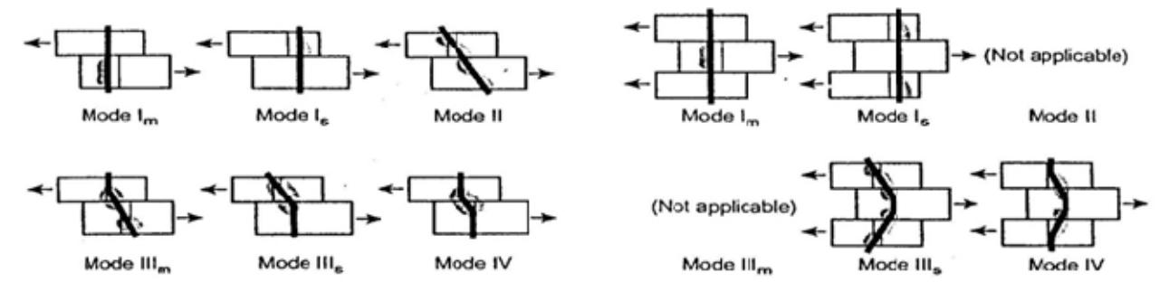
Figure 1. Yield modes on the connections (a) single shear (b) double shear Source: Soltis (1999)
The basic nail strength for different yield modes in the draft of Indonesian Timber Code (SNI-03-xxxx-2000) which is adopted from NDS (AWC, 2005) may be calculated by Equations (1) to (6). The experimental result of the multiple nail connections was compared to this design value to evaluate the group action factor. In the NDS 2005, besides number of nail; type of fastener, ratio of the axial stiffness of wood and side's plate, slip modulus between the main member and side's plates and spacing of the fastener were needed to determine the value of Cg. In this experimental study, the complicated equation of Cg in NDS 2005 for wood connection with plywood sides plate is going to be simplified based on number of nails. The single nail strength at possible failure modes are:
mode \[I_s\]: \(N_{Is} = \frac{3.3Dt_sF_{es}}{K_D}\) (1)
mode \[III_m\]: \(N_{IIIm} = \frac{3.3k_1DpF_{em}}{(1+2R_e)K_D}\) (2)
\[k_1 = -1 + \sqrt{2(1 + R_e) + \frac{2F_{yb}(1 + 2R_e)D^2}{3F_{em}p^2}}\] (3)
mode IIIs: \[N_{IIIs} = \frac{3.3k_2Dt_sF_{em}}{K_D(2+R_e)}\] (4)
\[k_2 = -1 + \sqrt{2 \frac{(1 + R_e)}{R_e} + \frac{2F_{yb}(1 + 2R_e)D^2}{3F_{em}t_s^2}}\]
(5)
mode IV: \[N_{IV} = \frac{3.3D^2}{K_D} \sqrt{\frac{2F_{em}F_{yb}}{3(1+R_e)}}\] (6)
where:
N = yield strength (N) \(K_D = 2.2 \text{ for } D \le 4.3 \text{ mm},\)
0.38D + 0.56 for 4.3 mm < D < 6.4 mm.
3.0 for D > 6.4 mm.
\(F_{em}\) = main member dowel bearing strength (MPa),
\(F_e = 16600 \text{ G}^{1.84} \text{ (psi)}\)
\(F_{es}\) = side member dowel bearing strength (MPa)
\(F_{vb}\) = dowel bending yield strength (MPa)
\(R_e = F_{em}/F_{es}\)
\(t_s\) = side member thickness (mm)
D = nail diameter (mm)
= nail penetration depth (mm)
The design of single nail strength N calculated by Equations (1) to (6). The wood and plywood properties to calculate single nail strength was based on the material properties test results as was shown in Table 1. And the design of adjusted single nail strength Z' calculated by Equation (7).
\[Z' = NC_M C_t C_{pt} C_{rt} C_d C_{di} C_{eq} C_{tn}\] (7)
adjusted design strength (N)
wet service factor temperature factor preservation factor fire resistance factor
penetration depth factor
diaphragm factor end grain factor toe-nail factor
All C factors was assumed to be 1.0 except for \(C_d\) and the design of connection strength Z calculated by Equation (8).
\[Z = n\phi_Z Z' \tag{8}\]
Z = design of connection strength (N)
n = total number of nail
\(\phi_z\) = resistance factor = 0.65
2. Method and Materials
This research based on the theoretical and experimental studies. The materials were tested based on the ASTM D143-94 standard testing for small clear specimen, ASTM 2005. The main member of the specimen was designed using sengon species which has lower specific gravity (G) than plywood, and meranti species which have higher specific gravity as shown in Table 1. The single row specimen was tested under uni-axial compression loading and the multiple rows connection was tested both under uni-axial compression and tension loadings.
Table 1. Average value of material data
| Material | G | Fc// (MPa) | Ft// (MPa) | mc (%) |
|---|---|---|---|---|
| Sengon 36x60 | 0.29 | 20.65 | 52.33 | 12 |
| Meranti 32x70 | 0.49 | 45.07 | 86.63 | 12 |
| Plywood 18x60 | 0.38 | 22.19 | 52.11 | 12 |
| Nail | diameter= 2mm | length= 40mm | Fyb=(130. 1000 | 4 – 214 d) (psi)*) |
*) NDS 2005
\(\dot{G}\) = specific gravity, Fc// = compression strength parallel to the grain, Ft// = tension strength parallel to the grain, mc = moisture content
Source: Rosiman (2007)
Table 2. Adjusted single nail design strength
| Туре | Yield Mode | Yield strength (N) | Adjusted nail strength*) (N) |
|---|---|---|---|
| \(I_s\) | 1 247.000 | ||
| Sengon- | \(III_{m}\) | 360.521**) | 330.478 |
| plywood | \(III_s\) | 417.908 | 330.476 |
| IV | 382.325 | ||
| Meranti- plywood | \(I_s\) | 1 247.000 | |
| \(III_{m}\) | 707.612 | 456 420 | |
| \(III_s\) | 531.712 | 456.438 | |
| IV | 497.932**) |
*) including \(C_{d}\), **) critical value, predicted failure mode Source: Rosiman (2007)
Based on the material properties in Table 1 and Equations (1) to (6), the design strength of a single nail was calculated. The result was then presented in Table 2. It was shown that the critical failure mode for sengon with lower specific gravity than plywood was mode III<sub>m</sub> and for meranti with higher specific gravity than plywood was mode IV. The design strength of the connections with multiple nails was as shown in Table 3.
Table 3. The design of connection strengt
| Туре | n | Connection strength Z * (kN) | ||
|---|---|---|---|---|
| \(2 \times 9 = 18\) | 3.867 | |||
| Sengon-plywood | \(2 \times 18 = 36\) | 7.733 | ||
| \(2 \times 27 = 54\) | 11.600 | |||
| \(2 \times 9 = 18\) | 5.340 | |||
| Meranti-plywood | \(2 \times 18 = 36\) | 10.681 | ||
| \(2 \times 27 = 54\) | 16.021 | |||
*) including \(\phi_Z\), without \(C_g\)Source: Rosiman (2007)
The variation of number of row and nails in one row on the specimens was shown as in Appendices, from Figure A to D and the experimental settings for three rows compression test and three rows tension test were described in Figures 2a and 2b. The test was done under displacement control at 0.6 mm per minute rate using universal testing machine.
(a)
Figure 2. Experimental settings (a) three rows compression test, (b) three rows tension test
3. Results and Discussion
3.1 The group action factor
The investigation was made to the group action factor at different level of strength, such as at proportional limit (\(C_{gp}\)), 5% offset nail diameter (\(C_{g5\%}\)) and ultimate (\(C_{gu}\)) as described in Figure 3. The compression tests result for single row was shown as in Table 4 and Figures 4 and 5. The \(C_g\) data for regression analysis was generated from the multiple nail strength divided by n times of single nail strength. Although the data were scattered and have a low \(R^2\), the result of \(C_g\) at different level of strength was close.
The result for three rows connection was shown as in Table 5 and Figures 6, 7 and 8. The result of \(C_g\) at compression test at proportional limit was lower than tension test, but the opposite result was occurred for \(C_{g5\%}\) and \(C_{gu}\) at three rows test. Although the data of three row test were scattered but the \(R^2\) was higher than single row test.
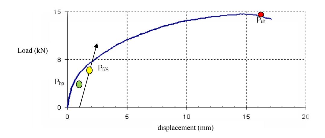
Figure 3. Typical load vs deflection curve of the connection
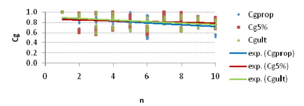
Figure 4. Group action factor of one row sengon-plywood nail connection
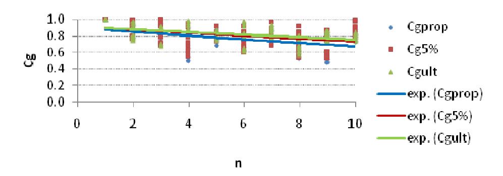
Figure 5. Group action factor of one row meranti-plywood nail connection
Table 4. Group action factor for single row
| Specimen | Force | Equations*) | \(\mathbb{R}^2\) |
|---|---|---|---|
| Pbp | \(C_{gp} = 0.906 e^{-0.02n}\) | 0.13 | |
| Sengon-plywood | P5% | \(C_{g5\%} = 0.863e^{-0.01n}\) | 0.23 |
| \(P_{ult}\) | \(C_{gu} = 0.912 e^{-0.01n}\) | 0.13 | |
| 16 | \(P_{bp}\) | \(C_{gp} = 0.898 \text{ e}^{-0.02n}\) | 0.18 |
| Meranti- plywood | P5% | \(C_{g5\%}^{er} = 0.921e^{-0.02n}\) | 0.14 |
| \(P_{ult}\) | \(C_{gu} = 0.920 e^{-0.02n}\) | 0.19 |
*) without outlier
Table 5. Group action factor for three rows
| Specimen | Force | Equations*) | \(\mathbb{R}^2\) |
|---|---|---|---|
| \(P_{bp}\) | \(C_{gp} = 0.989 e^{-0.03n}\) | 0.56 | |
| Compression (-) | P5% | \(C_{g5\%} = 1.020 e^{-0.02n}\) | 0.57 |
| \(P_{ult}\) | \(C_{gu} = 0.959 e^{-0.01n}\) | 0.28 | |
| \(P_{bp}\) | \(C_{gp} = 1.023 e^{-0.03n}\) | 0.67 | |
| Tension (+) | P5% | \(C_{g5\%}^{e} = 0.995 e^{-0.02n}\) | 0.54 |
| \(\mathbf{P}_{\mathrm{ult}}\) | \(C_{gu} = 0.938 e^{-0.02n}\) | 0.31 |
*) without outlier
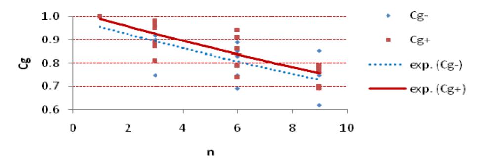
Figure 6. Group action factor of three row nail connection at the proportional limit
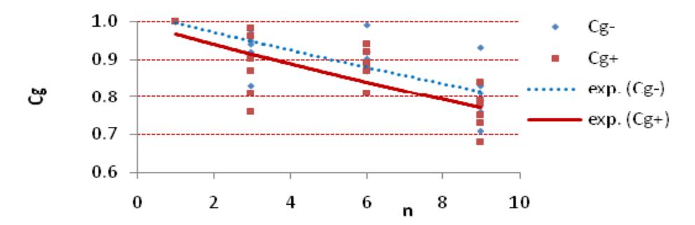
Figure 7. Group action factor of three row nail connection at the 5% offset nail diameter
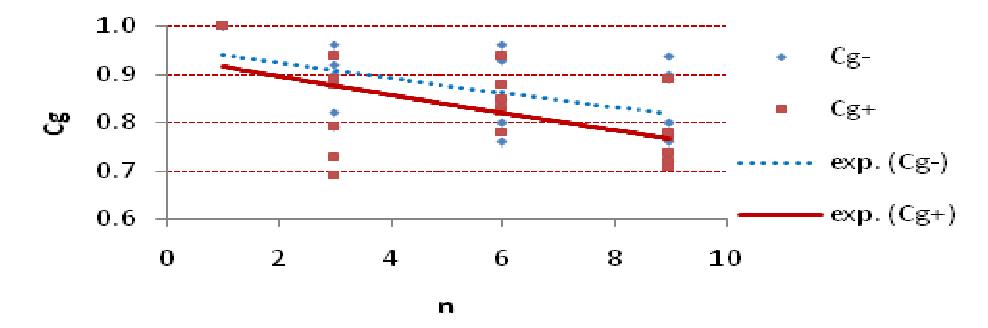
Figure 8. Group action factor of three row nail connection at the ultimate strength
Based on the single and multiple rows tests, the proposed conservative simplified group action factor Cg = e -0.03(n-1) based on Cg =1 for n =1, and Cg = 0.76 for n=10 which is observed manually may be used for design connection with plywood sides plate.
3.2 The strength of connections
The comparison of the experimental strength to the design value was done for both types of specimen as shown in Figures 9 and 10. The result showed that the strength at proportional limit and 5% offset was lower than the design value. It means that without considering Cg the connection will exceed the elastic limit under design load. But the ultimate strength could achieve 2.5 to 3.0 times the design value as was shown in appendices Table A and Table B, giving a significant safety factor to prevent collapse.
3.3 The failure modes
The Failure modes on sengon connection with lower specific gravity than plywood was mode IlIm and for meranti connection with higher specific gravity than plywood was mode IV, match with the value prediction in Table 2.
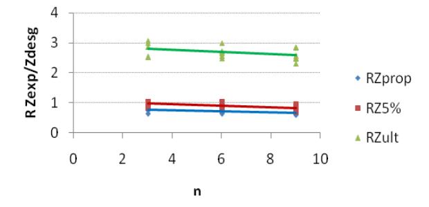
Figure 9. Ratio of experimental to design strength of sengon-plywood connection
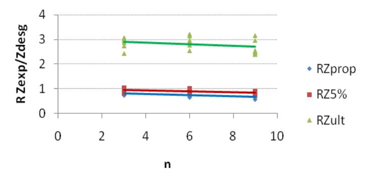
Figure 10. Ratio of experimental to design strength of meranti-plywood connection
Figure 11. Failure at three rows - six nails tension specimen (a) sengon-plywood (b) meranti-plywood
At tension test as was shown in Figures 12 to 15, the nail in sengon-plywood was fail in single curvature and in the meranti-plywood fail in double curvature because the higher specific gravity of meranti.
Plywood has more damage both outside or inside at meranti-plywood connection. The main wood member has more damage for sengon-plywood.
Figure 12. Nail failure modes (a) sengon-plywood - mode IIIm, (b) meranti-plywood - mode IV
Figure 13. Damage on the outside surface of plywood sides plate, (a) sengon-plywood (b) meranti-plywood
Figure 14. Damage on the inside surface of plywood sides plate, (a) sengon-plywood (b) meranti-plywood
Figure 15. Damage on the surface of wood main member, (a) sengon-plywood (b) meranti-plywood
4. Conclusions
- 1. The experimental value of the connection strength at proportional limit and 5% offset diameter was found in between 0.7-1.0 of the strength design based on the draft of Indonesian Timber Code (SNI-03-xxxx-2000). It means that the design strength (without \(C_g\)) slightly exceeded the elastic range under the design load.
- 2. The ultimate strength is more than 2.5 times of the design strength will give a satisfied safety factor from near collapse.
- 3. It was proof that the failure modes prediction by yield limit equations was accurate and the equations can be applied to calculate the strength of wood connection with plywood side's plate.
- 4. The proposed simplified group action factor \(C_g = e^{-0.03(n-1)}\) may be used for the design connection with plywood side plates to maintain the connection remain in the elastic range under the design load.