
Abstrak
Penelitian ini adalah tentang pengembangan sebuah model komputasi yang dapat mensimulasikan aliran yang melewati saluran samping jalan dalam sistem drainase komplek perumahan yang mempunyai lahan yang sangat landai dalam kondisi tidak bergantung waktu. Persamaan pengaturnya adalah persamaan aliran seragam Manning yang telah digunakan secara luas di seluruh dunia. Persamaan tersebut diselesaikan dengan menggunakan metode Newton-Raphson. Model ini diaplikasikan untuk mensimulasikan aliran saluran samping jalan dalam sistem drainase Perumahan Kharismatama Permai di Padang, yang sering banjir akibat sisa hujan. Intensitas curahan hujan diukur secara manual pada waktu yang sama banjir terjadi pada komplek perumahan tersebut. Jenis bahan tubuh saluran diamati untuk menentukan koefisien kekasaran saluran, dan jenis penutup lahan juga diamati untuk menentukan koefisien limpasan. Dengan mengatur kemiringan saluran dan mengubah arah alirannya, sistem drainase tersebut dapat mengalirkan sisa hujan tanpa banjir.
Kata-kata Kunci: Curahan hujan, saluran samping jalan, debit, kemiringan, arah aliran, model.
1. Introduction
When a rainfall with a high intensity falls on a very mild-slope housing land, the rainfall excess then slowly flows to roadside gutters across the land. The water then slowly flows following the gutter slopes. Consequently, the water depth increases significantly. A lower gutter gravitationally receives an additional flow from an upper gutter in case of both gutters are linked. As a result, the lower gutters automatically
convey the greater flow than the upper gutters do. A lower gutter may be linked by more than one of upper gutters. This may cause the water overflowing in the lower gutters.
The situation mentioned above frequently happened in some residential areas with a very mild-slope land. To solve this problem, the rate of the conveyance of gutter sections should be increased. The width of the gutters cannot be widened, since it can narrow the road width. Instead, the slope of the gutters (and also the flow directions) can be adjusted to get rid of flooding.
As a result, the present study devotes to solving overwhelming rainfall excess in residential areas with a very mild-slope land by considering the adjustment of the gutter slopes and the flow directions to increase the rate of the conveyance of gutter sections. Consequently, the primary objective of the present study is to develop a computational model, which is capable of predicting the water depth in every segment of the gutter in a residential area with a very mild-slope land. To do this, some secondary objectives are needed, i.e.: (1) surveying to find a residential area with a very mildslope land, which is frequently overwhelmed by the rainfall excess; (2) measuring the rainfall intensity in the considered residential area; (3) measure the geometric of gutters in the considered residential area; (4) observing the types of gutter materials in the considered residential area; and (5) observing the land covers in the considered residential area.
2. Governing Equation
As referred by Wikipedia (2010), an Irish engineer, Robert Manning in 1890, presented a formula, which was modified to its present well-known form, i.e.
\[v = \frac{1}{n} R^{\frac{2}{3}} S^{\frac{1}{2}} \tag{1}\] where v is the average horizontal velocity of flow in m/ s; n is the roughness coefficient of Manning; R is the hydraulic radius in m; and S is the gutter slope in m/m. The hydraulic radius R is obtained from the water area A divided by the wetted perimeter P. The values of the roughness coefficients n were tabulated by Chow (1973), and the values of S and the geometric of the gutters are obtained by measurement.
The velocity can be expressed as
\[v = \frac{Q}{A} \tag{2}\] where Q is the flow or discharge in m<sup>3</sup>/s. As a result, the Equation (1) leads to
\[Q = \frac{1}{n} A R^{\frac{2}{3}} S^{\frac{1}{2}}\] (3)
Due to the Equation (3) is a steady state one, the peak flow should be used in the case of a small watershed. This was confirmed by Bedient and Huber (1992) that urban development of a natural basin or watershed will usually result in increased peak outflows and shorter responses times as development proceeds. Small watershed designs usually involve the use of either the rational method or a unit hydrograph procedure to predict peak flows at various places for a given design rainfall and duration. The rational method is then used since it is the simplest rainfall-runoff formula. More detailed Bedient and Huber (1992) explained that the concept behind the rational method lies in the assumption that a steady, uniform rainfall rate will produce maximum run-off when all parts of a watershed are contributing to outflow, a condition that is met after the time of concentration to has elapsed. The rational method can be expressed as
\[Q = C i A_{ws}\] (4)
in which Q is the peak flow; C is the run-off coefficient; i is the rainfall intensity in m/s; and Aws is the watershed area in square meter. The values of the coefficients C with respect to return periods of 2, 5, 10, 25, 50, 100 and 500 years can be found in Chow et al. (1988). The flow Q conveyed by a gutter is assumed to be a constant along the considered gutter.
The water area A and the hydraulic radius R are function of the water depth y, so that the solution of the Equation (3) is the water depth.
3. Numerical Solution Algorithm
Since R = A / P, Equation (3) can be expressed as
\[Q = \frac{1}{n} \frac{A^{\frac{5}{3}}}{p^{\frac{2}{3}}} S^{\frac{1}{2}}\] (5)
\[\frac{Qn}{S^{\frac{1}{2}}} = \frac{A^{\frac{5}{3}}}{P^{\frac{2}{3}}} \tag{6}\]
If Equation (6) powered by 3/2 leads to
\[\left(\frac{Qn}{S^{0.5}}\right)^{1.5}P - A^{2.5} = 0 \tag{7}\]
Every single gutter is assumed to be a prismatic channel. For a gutter with a rectangular section as shown in Figure 1, the water area A and the wetted perimeter P can be stated respectively as
\[A = by (8)\]
\[P = b + 2v \tag{9}\]
Figure 1. Rectangular section
Due to P and A are a function of y, Equation (7) can be expresses as
\[f(y) = aP - A^{2.5} = 0 \tag{10}\] where:
\[a = \left(\frac{Qn}{S^{0.5}}\right)^{1.5} \tag{11}\]
Substitution of Equations (8) and (9) into Equation (10) gives
\[f(y) = a(b+2y) - (by)^{2.5}\] (12)
The differential form of Equation (12) with respect to the water depth v is
\[\frac{df(y)}{dy} = f'(y) = 2a - 2.5bA^{1.5}\] (13)
Now, the water depth y can be solved using the Newton-Raphson method (Kreyszig, 1988)
\[y_{i+1} = y_i - \frac{f(y_i)}{f'(y_i)}\] (14)
where the initial value \(y_1\) is an arbitrary value and \(y_2\) is y value in the first iteration. The iteration should be stopped if
\[\left| \mathbf{y}_{i+1} - \mathbf{y}_{i} \right| \le 0.001 \tag{15}\]
4. Field Measurement and Observation
A field measurement is conducted by Dewi (2008) to collect all gutter-related parameters i.e. the gutter width b; the gutter depth d; the gutter lengths; and the gutter slope S. Such measurement was applied to all roadside gutters in the housing of Kharismatama Permai in Padang (see Figure 2). The measurement of the parameters b, d and the length of the gutters was done by using a meter tape or a rod (a staff). However, to collect the data of the gutter slopes S, the elevation of the slope bases was measured by using a water-pass. The watershed area Aws was also measured to predict the flow Q.
Figure 2. Kharismatama permai housing (Google Earth image, 2010)
During the measurement, the materials of the gutters are also inspected to determine the roughness coefficients of Manning. Overall, the gutters were made from unfinished concrete. This gives the roughness coefficient of Manning n = 0.20 (Chow, 1973).
To predict the rate of rainfall intensity in a given area especially for designing a drainage system, the use of rainfall data with short periods is strongly recommended. However, these data are unavailable in Padang, but daily rainfall data. As a result, we measured it manually by using a cylinder and a stopwatch. The measurement was done at the same time when flood occurred in the housing of Kharismatama Permai. The measurement gave 136 mm/hour for the rate of rainfall intensity.
As a comparison, the maximum daily rainfall data recorded by Tabing weather station in Padang, i.e. the nearest station to the considered housing, from year 1986 to 2008 gives an average of 287.6 mm a year with a standard deviation of 195.6 mm (in the logs of data gives an average of 2.3920 a year with a standard deviation of 0.2268 and a skewness of 1.4551). Since the data are extremes (maxima), an extreme probability distribution model, say the Log-Pearson type 3 distribution, can be used to predict the quantity of rainfall for certain return periods T. If the Mononobe formula is used to predict the rate of rainfall intensity, an IDF (intensity, duration, frequency) curve can be made as shown in Figure 3. The intensity rate of the measurement result is comparable to that of the prediction results for the return period of 50 years with a duration of 4 hours. In the reality, the rate of about 136 mm/ hour (as one measured manually) occurred frequently especially in rainy season in every year from year 1986 to 2008. This was confirmed by some residents of the housing. This phenomenon indicates that short period data should be used in predicting the rate of rainfall intensity.
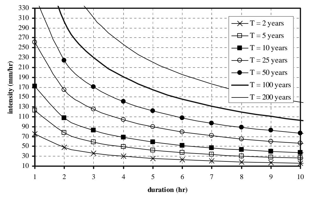
Figure 3. IDF curve based on the maximum daily rainfall
The land covers in the housing of Kharismatama Permai in Padang were also observed to determine appropriate values for run-off coefficients C. Generally, the surface layers of the roads in the considered residential area were asphalts. If the roads are presumed to cover the area about 20%, and about 80% of the rest (i.e. 64%) is covered by concrete and roof, and the rest is about 16% for the grass area such as lawns and parks. Based on Chow et al. (1988) for a return period of 50 years, the run-off coefficients are 0.9 for the roads, 0.92 for concrete and roof, and 0.44 for grass. By considering an area-weighting factor gives an average value for C = 0.84.
All parameters obtained are inserted to the governing equation to predict the water depths in every gutter segment. Based on the measurement, the existing flow directions can be identified as shown in Figure 4
5. Numerical Set-up
The present numerical model is applied to simulation of the existing flow directions flowing in the road side gutters in the housing of Kharismatama Permai as shown in Figure 4. The numerical results are shown in Table 1.
Table 1 shows that 13 gutters are overflowed, i.e. gutters with numbers 2, 5, 7, 10, 14, 15, 17, 24, 26, 28, 29, 30 and 31. Gutters with numbers 2, 17, 24, 26 and 29 are blocked at the downstream. Meanwhile, gutters with numbers 14, 15, 28, 30 and 31 cannot convey flow due to their slopes being flat. The present model is capable of identifying the overflowed gutters as they happen in the considered real drainage system.
To solve these problems, some flow directions are changed; base slopes are adjusted and culverts are added to connect one gutter to another as shown in Figure 5. The numerical results based on the reviewed conditions are shown in Table 2.
Tabel 2 shows that all gutters are capable of conveying flows properly without overflowing. This is done by:
- 1. adjusting all the slopes of the gutters except the gutters with numbers 3, 6, 9, 12, 16, 17, 18, 19, 21 and 22;
- 2. changing flow directions of the guters with numbers 2, 4, 5, 14, 15, 24, 25, 26, 27, 28, 29, 30 and 21;
- 3. adding a culvert at the downstream of the gutters with numbers 7, 24, 25, 26, 27, 28, 30 and 31.
6. Conclusions
- 1. A numerical model, which is applicable of simulation of flows flowing through road side gutters across a housing drainage system with a very mildslope land in a steady state condition, is developed.
- 2. The governing equation is the world-widely used uniform flow formulation of Manning. The governing equation is solved using the Newton-Raphson method.
- 3. Comparison between the present numerical model results and the field data shows that the present model is capable of identifying the overflowed gutters as they happen in the considered real drainage system.
7. Recommendations
The present model still needs to be verified by comparing the results of the present model based on the reviewed condition to the field data. Of course, this is very expensive, because the considered real drainage system has to be re-dug following the recommendation of the present model results. Alternatively, it can be done by making a physical model in a laboratory.
8. Acknowledgements
The present authors would like to thanks to the Directorate General of Higher Education Indonesia for its financial support through the Fundamental scheme of a contract No: 126.b/H.16/PL/HB-PID/IV/2009, date 20 April 2009.