
Abstrak
Pengamatan eksperimental pada model pelimpah digunakan dalam penelitian ini. Tiga konfigurasi penempatan baffle digunakan dalam percobaan. Energi sepanjang aliran di atas spillway dihitung berdasarkan kedalaman aliran dan debit yang diukur selama percobaan. Variasi kedalaman aliran dan debit ditentukan berdasarkan tinggi baffle sebagai referensi. Percobaan dilakukan dalam flume 7 meter panjang lebar 0,078 m. Model spillway memiliki dimensi tinggi 17,2 cm, mercu bulat dan kemiringan hilir 1: 1. Tidak ada struktur yang ditempatkan di hilir spillway. Debit yang diterapkan pada model pelimpah berada dalam kisaran 0,6 hingga 1,8 l/s. Hasil eksperimen menunjukkan bahwa hasil optimal disipasi energi diperoleh ketika kedalaman aliran sama dengan ketinggian baffle. Disipasi energi yang diamati dalam penelitian ini adalah sekitar 30% sampai 50% pada energi yang masuk dari aliran yang melalui pelimpah. Dalam eksperimen diamati bahwa panjang loncatan hidrolik berkurang karena penerapan baffle pada saluran peluncur.
Kata Kunci: Disipasi energi, spillway, baffled chute, loncatan hidrolik.
1. Introduction
High demand of fresh water for domestic, agricultural and industrial needs, hydropower generation and flood control results in many project for creating reservoir to control water storage. A reservoir is usually consists of dam, reservoir, intake structures, diversion and spillway. A good energy dissipation is needed to protect downstream reach of a spillway. A flow through spillway, at the downstream, has high kinetic energy which is transformed from potential energy caused by water surface elevation at the reservoir. This kind of energy needs to be controled in order to avoid damages of the structures where the water flowing over. This paper shows the results of experimental study on the energy dissipation through a baffled chute.
Energy dissipation of flow over spillway may take place during entrance, along the chute, along a trajectory of jet flow in the air, during the plunging of the jet and in a hydraulic jump (Novak et al., 2007). According Vischer (1995) there are many mechanism in dissipating flow energy, i.e. by sudden expansions, by abrupt deflections, by counterflows, by rough walls, by vortex devices, and by spray inducing devices. Two basic types of energy dissipators are hydraulic jump-type and impact-type energy dissipators. At the hydraulic jump-type energy dissipator, the energy is dissipated through the high turbulence of flow at the hydraulic jump. At the impact-type energy dissipators, flow is directed towards obstructions at wich the flow direction will be diverted to other directions, creates turbulence and dissipates flow energy. The impacttype energy dissipators are usually shorter than hydraulic jump-type ones, and preferred for conditions when space is limited.
Placement of baffles as impact type energy dissipator along the chute is common (Khatsuria, 2005). However, it may not be economical. It is suggested that at least five rows of baffles are placed at the end of a chutes. The baffles will limit flow acceleration in between rows of baffle and reduce the flow velocity at the toe of the chute.
2. Methodology
Specific energy of the flow in open channel could be analyzed through its flow depth and velocity. Effectivity of baffled chute were analyzed based on the reduction of energy compared to its initial energy before drop. In the experiments, measured variables were: discharge, water surface and channel bed elevation and water depth. Effect of baffle configurations were studied through baffle spacing and placement of starting point of the baffle group.
Experiments were conducted in a 7 meters long glasssided flume of 7.7 cm wide. The bed of flume was set at a mild slope. The flume was equipped with a recirculating pump and venturimeter. Discharge was computed from the pressure difference at venturimeter. Pressure readings were obtained by a digital pressure meter connected to the pressure ports of venturimeter.
Baffle blocks are made of cube-shaped wood material of size 1 x 1 x 1 cm. Spacing between baffle blocks in the streamwise direction were 2 cm and 4 cm. Spacing
between baffle blocks in the transverse direction was 1 cm. The setup of experiments were:
- Setup 0: without baffle blocks
- Setup 1: with baffle blocks, 2 cm spacing stream wise direction.
- Setup 2: with baffle blocks, 4 cm spacing stream wise direction.
- Setup 3: with baffle blocks, 2 cm spacing stream wise direction, covers only half part downstream.
Applied flow discharges were determined based on flow depth over spillway. Discharges at which the flow depths of 0.5 , 1.0 and 2.0 cm are 0.6, 1.0 and 1.9 l/s respectively. Photographs of fow profiles over the chute are presented in Figure 2 to Figure 4 .
Flow depths were measured at upstream of the spillway, at the spillway crest, in the midle between crest and the toe of spillway, and at the toe of the spillway.
3. Data Analysis
Based on overall results of experiments, placement of baffle block at the chute significantly reduce the flow velocity at the toe of spillway. At low flow condition, setup 3 gives maximum reduction on the flow velocity at the toe of spillway, while setup 2 gives maximum reduction at high flow condition. Flow reduction at medium flow discharge is similar for all setup using baffle blocks. This may bring into conclusion that in low to medium flow condition, setup 3 which has less baffle blocks has a better performance in reducing flow
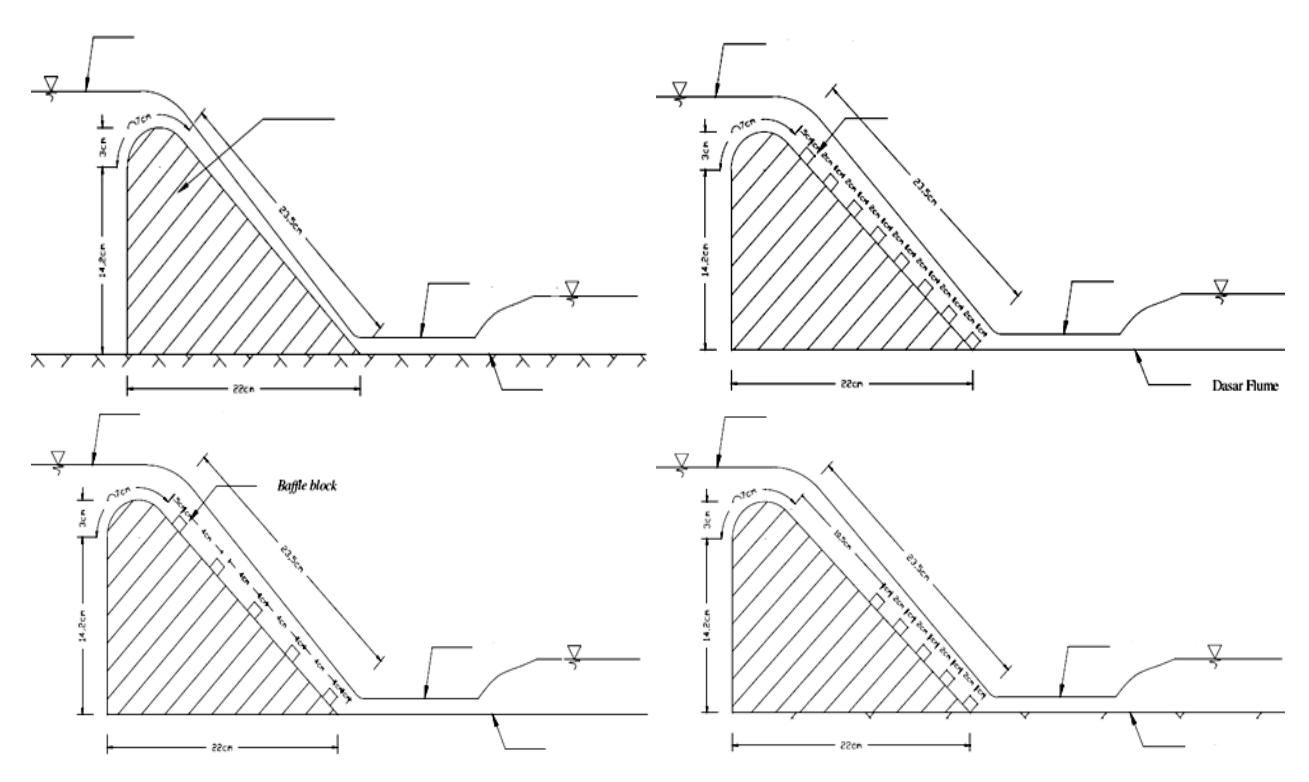
Figure 1. Configuration of baffle placement in the stream wise direction.
Figure 2. Flow over the chute at experiments with flow discharge of 0.6 l/s
Figure 3. Flow over the chute at experiments with flow discharge of 1.0 l/s
Figure 4. Flow over the chute at experiments with flow discharge of 1.9 l/s
velocity to those of setup 1 and 2. The occurrence of impact at first row of baffle blocks at setup 3 is probably the main factor of its performance. This kind of mechanism was not observed in the setup 1 and setup 2. At setup 1 and 2, the flow over the chute gained higher velocity as the flow accellerated over the baffle for a long distance.
In term of energy reduction, energy loss for setup 0 were in the range of 32 to 54 %. This result shows least energy reduction was obtained for low flow condition, and maximum energy loss observed for high flow condition. Different trend were observed for setup-1 to setup-3. These setups showed that energy reductions were less for high flow condition. The energy reduction was lower for higher flow condition because relative degree of obstruction will be less. This may be expected as relative size of baffle is less for a high flow condition.
4. Conclusion
Following conclusions are withdrawn from the research:
1. It was found that placing initial row of baffle just after the crest of spillway is not effective. This is
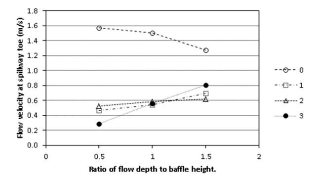
Figure 5. Graphs of flow velocity at toe of spillway vs. ratio of flow depth to baffle height.
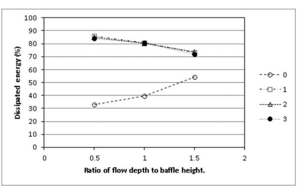
Figure 6. Graphs of dissipated energy (%) vs. ratio of flow depth to baffle height.
- due to the flow is still in acceleration and has a relatively low velocity.
- 2. Longer spacing in longitudinal direction will reduce the effectivity. This is because the resistance is less and acceleration is developing in between row of baffles towards downstream.
- 3. Less lateral spacing will reduce resistance as the flow will flow over the baffle and reduce the energy dissipation over baffled chute.
- 4. Flow depth of design discharge over the chute without baffle is suggested to be a practical baffle height reference.
5. Acknowledgment
The author would like to thank to Water Resources Engineering Laboratory, Faculty of Civil and Environmental Engineering, ITB and Mr. Prayoga, undergraduate student of Civil Engineering Study Program, which involved in the experimental data collection.