
Abstrak
Jalan Tol memiliki peran penting terhadap perkembangan ekonomi sehingga memerlukan standar pelayanan minimal (SPM) yang mantap, sebagaimana tertulis dalam PP No.34 tahun 2006 tentang jalan. Jalan tol Cipali beroperasi di tahun 2015 yang menghubungkan Cikampek ke Palimanan. Oleh karenanya penting untuk dilakukan pemeliharaan struktural dengan lapis tambah agar struktur perkerasan tetap mantap dalam menopang beban repetisi yang terus bertambah. Penelitian ini bertujuan untuk menganalisis tebal lapis tambah menggunakan prosedur mekanistik AUSTROAD 2010 dengan program CIRCLY dan program KENLAYER untuk wilayah studi tol Cipali antara KM110+000 hingga KM115+000. Analisis yang dilakukan menghasilkan tebal lapis tambah yang menggunakan program CIRCLY membutuhkan tebal minimum 170 mm untuk model 2 lapisan dan 3 lapisan (arah menuju Subang) dan 160 mm untuk model 2 lapisan dan 150 mm untuk model 3 lapisan (arah menuju Palimanan). Kebutuhan tebal lapis tambah menggunakan program KENLAYER (elastik linier) arah Subang 160 mm untuk model 2 lapisan dan 130 mm untuk model 3 lapisan, sedangkan arah Palimanan adalah 140 mm untuk model 2 lapisan dan 100 mm untuk model 3 lapisan. Apabila menggunakan program KENLAYER elastik non-linier arah Palimanan adalah 120 mm untuk model 2 lapisan dan 80 mm untuk model 3 lapisan. Untuk arah Subang adalah 140 mm untuk model 2 lapisan dan 100 mm untuk model 3 lapisan.
Kata Kunci: Perkerasan lentur, AUSTROAD 2010, KENLAYER, CIRCLY, lapis tambah
1. Introduction
Toll roads have an important role on the economic development, therefore it is necessary to make road improvements to increase the road serviceability or minimum service standards (MSS), as described in the Indonesian Government Regulation No. 34 of 2006 on roads, covers two things; 1.) road network with accessibility, mobility and safety performance indicators 2.) road segments with road condition and speed performance indicators. Meanwhile, the performance of road pavement is largely modeled as a function of several factors defined as road damage which causes both structural and functional deterioration.
Treatment of road damages is intended so that the road network can still carry out its role properly. This can be fulfilled if the existing road is in a good condition. Based on these conditions, it is necessary to perform a re-evaluation to find out the existing road conditions.
Today, a trend to use computer programs in designing and analyzing pavement materials has been developed, however, each program has its own specifications of abilities and limitations in carrying out the analysis. Because of the elaboration above, we tried to do a research with the main topic of comparison of the thickness of flexible pavement overlay using Austroad 2010 and the Kenlayer program.
The mechanistic procedure method released by Austroad 2010 is assisted by the Cirlcy program, which is a method that uses an analytical approach with a multi-layer structural model and calculations based on stress and strain and deformations caused by loading (Ajitomo.2012), and Kenlayer is a mechanistic procedure method by Huang that also uses a multi-layer structural model. In Circly, the pavement structure is considered to be a linear elastic pavement structure related to the response caused due to stress from vehicle loading, while in Kenpave, the pavement structure material is considered to be different; that is linear elastic, non-linear elastic or viscous elastic, where to know the strain that occurs either under the asphalt (єt) or above the sub grade (єc), it is necessary to input pavement data such as modulus, poisson ratio, radius of contact area, distance between wheels (x axis) and distance between vehicle axes and coordinates of the point to review (z axis).
2. Literature Review
2.1 Austroad 2010 method
The AUSTROAD method is a pavement overlay planning calculation method using analytical or mechanistic methods, which the calculations are carried out based on stress, strain, and deformation of the pavement structure that is loaded. To simplify the calculations, a nomogram or computer programs can be used.
In a planning using the Austroad Method, one of the computer programs that can be used is Circly. The parameters used in the Austroad method are;
- Age of Plan
- Traffic Growth
- Strength of Subgrade
- Planned Traffic
- Elasticity Parameters
- Weighted Mean Annual Pavement Temperature (WMAPT)
By using the Circly program output in the form of tensile strains that occur below the surface of the asphalt and the compressive strain above the subgrade, the allowable repetitive load can be calculated based on 2 criteria, which are;
Fatigue Criteria:
\[N = RF \left[ \frac{6918(0,856 Vb + 1,08)}{Smix^{0,36} \mu \varepsilon} \right]^{5}\] (1)
Permanent Deformation Criteria:
\[N = \left[\frac{9300}{u\varepsilon}\right]^7 \tag{2}\]
2.2 Kenlayer computer program
One of the computer programs that can be used for flexible pavement structures is the Kenlayer program. The Kenlayer program is a part of the Kenpave program which can be used for flexible pavement structures.
In general, the output is in the form of stress, strain, and deflection at the point to analyze. In addition, the form of case model to analyze can also be seen on LGRAPH on the Kenlayer main menu. By using the Kenlayer program output in the form of a test strain and compressive strain, the allowable repetitive load can be calculated based on 2 criteria, which are;
Fatigue Criteria:
\[Nf = f1(\varepsilon t)^{-f2}(E1)^{-f3} \tag{3}\]
Permanent Deformation Criteria:
\[Nf = f4(\varepsilon c)^{-f5} \tag{4}\]
Table 1. The constant value based on laboratory experiments (Huang, 2014)
| Factor | Asphalt Institute | Shell |
|---|---|---|
| f1 | 0,0796 | 0,0685 |
| f2 | 3,291 | 5,671 |
| f3 | 0,854 | 2,363 |
| f4 | 1,365 x 10-9 | 6,15 x 10⁻⁷ |
| f5 | 4,477 | 4,0 |
3. Research Methods
The research methodology used in this study refers to the scope of research in order to achieve the research objectives. This can be seen in the research flow chart.
The flowchart in the research of the thickness of flexible pavement overlay using the AUSTROAD 2010 method and the KENLAYER program can be seen in the following figure 1.
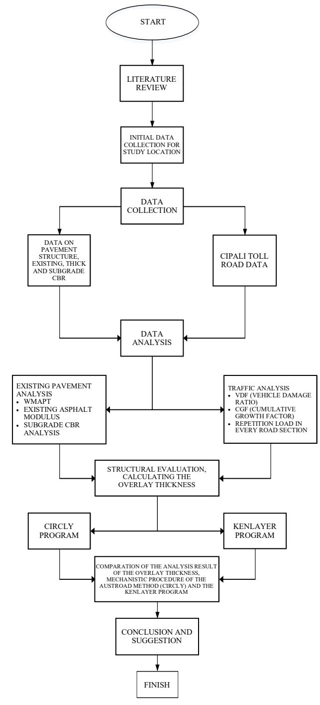
Figure 1. Research Framework
4. Data Presentation and Analysis
4.1 Traffic data and growth rate
The historical data on traffic volume was obtained from the recapitulation of daily traffic data based on the class of vehicles that passed through the CIPALI toll road from Subang to Palimanan. This data can be used to see the growth rate of vehicles. The data is described in Table 2 below:
Table 2. Annual traffic volume for 3 years at Cipali toll road (2015–2017)
| V | Number of vehicles | ||||
|---|---|---|---|---|---|
| Year | Class I | Class II | Class III | Class IV | Class V |
| 2015 | 6.109.924 | 751.339 | 163.594 | 14.332 | 9.737 |
| 2016 | 12.862.830 | 1.729.382 | 349.810 | 40.958 | 38.515 |
| 2017 | 12.957.897 | 1.758.119 | 444.184 | 45.796 | 59.921 |
| Total | 31.930.651 | 4.238.840 | 957.588 | 101.086 | 108.173 |
Referring to the Figure 2, the traffic volume of vehicles passing through the Cipali toll road continued to increase from 2015 to 2017. In 2015, the total number of vehicles passing through the Cipali toll road was 7,048,916 vehicles. This number increased to 15,031,495 vehicles in 2016 and continued to increase to 15,265,917 vehicles in 2017.
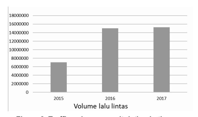
Figure 2. Traffic volume recapitulation in the year of 2015 - 2017
4.2 Design traffic analysis
A. Design traffic analysis
Referring to the Table 4, based on the results of the analysis, the number of repetitions of vehicles heading towards Subang in the planned year of 2022 is 8.39 x \(10^7\) ESA. This value shows that the existing pavement structure must be able to withstand the load which will be forwarded to the subgrade until 2022 for this value, so that fatigue or permanent deformation does not occur.
Unlike the direction to Palimanan, based on the results of repetition load analysis, the design of the direction to Subang has a greater number of repetition loads, which is 8.39 X 10⁷ as reported in the table above, this of course will affect the amount of minimum overlay thickness needed until the planned year of 2022.
Table 3. Cipali toll road traffic load, Km 110 + 000 to 115 + 000 using the AUSTROAD method
| Presumptive | |||
|---|---|---|---|
| Year | DESA | DSAR5 | DSAR7 |
| 2018 | 3,04E+06 | 3,35E+06 | 4,87E+06 |
| 2019 | 6,28E+06 | 6,91E+06 | 1,00E+07 |
| 2020 | 9,73E+06 | 1,07E+07 | 1,56E+07 |
| 2021 | 1,34E+07 | 1,47E+07 | 2,14E+07 |
| 2022 | 1,73E+07 | 1,90E+07 | 2,77E+07 |
| 2023 | 2,15E+07 | 2,36E+07 | 3,44E+07 |
| CESA | 4,98E+07 | 5,47E+07 | 7,96E+07 |
Table 4. Cipali Toll Road planned traffic load, Km 115+000 to 110+000 using the AUSTROAD method
| Presumptive | |||||
|---|---|---|---|---|---|
| Year | DESA | DSAR5 | DSAR7 | ||
| 2018 | 5,13E+06 | 5,64E+06 | 8,21E+06 | ||
| 2019 | 1,06E+07 | 1,16E+07 | 1,69E+07 | ||
| 2020 | 1,64E+07 | 1,80E+07 | 2,62E+07 | ||
| 2021 | 2,26E+07 | 2,49E+07 | 3,61E+07 | ||
| 2022 | 2,92E+07 | 3,21E+07 | 4,67E+07 | ||
| 2023 | 3,62E+07 | 3,98E+07 | 5,79E+07 | ||
| CESA | 8,39E+07 | 9,23E+07 | 1,34E+08 | ||
B. Overlay thickness analysis using the AUSTROAD mechanistic procedure
The calculation of the overlay thickness using the Austroad 2010 mechanistic procedure method was carried out with the help of the Circly program, both for the direction from Subang to Palimaan and from Palimanan to Subang, for the planned year 2022, where the existing pavement model was assumed to consist of 2 layers and 3 layers. The results of the minimum overlay thickness requirements obtained are;
Table 5. Circly's minimum overlay thickness: Subang - Palimanan
| Results | Allowable Repetition | Design Repetition | ||
|---|---|---|---|---|
| 2 Layer | Thickness | 160 | ||
| Tensile | 1,26E-04 | 6,50E+07 | ||
| Compresive | 2,16E-04 | 1,70E+11 | 4,98E+07 | |
| Results | Allowable Repetition | Design Repetition | ||
| 3 Layer | Thickness | 150 | ||
| Tensile | 1,31E-04 | 5,50E+07 | 4,98E+07 | |
| Compresive | 2,33E-04 | 1,01E+11 | ||
Table 6. Circly's minimum overlay thickness: Palimanan - Subang
| Results | Allowable Repetition | Design Repetition | ||
| 2 Layer | Thickness | 170 | ||
| Tensile | 1,89E-04 | 8,90E+07 | ||
| Compresive | 2,06E-04 | 2,38E+11 | 8,39E+07 | |
| Results | Allowable Repetition | Design Repetition | ||
| 3 Layer | Thickness | 170 | ||
| Tensile | 1,45E-04 | 1,06E+08 | ||
| Compresive | 2,13E-04 | 1,92E+11 | 8,39E+07 | |
C. Overlay thickness analysis using the kenlayer program
In the overlay thickness calculation using the Kenlayer program, the properties of the material are divided into 2 types; linear and non-linear to the loading responses.
The output of this program is in the form of tensile strains under the asphalt layer and compressive strain on the subgrade that was used to find the allowable loading from the modeled pavement structure. However, the minimum overlay needed can be seen in the table below:
Table 7. Linier kenlayer's minimum overlay thicknes: Subang - Palimanan
| Results | Allowable Repetition | Design Repetition | ||
| 2 Layer | Thickness | 140 | ||
| Tensile | 1,29E-04 | 3,34E+14 | ||
| Compresive | 3,18E-04 | 6,02E+07 | 4,98E+07 | |
| Results | Allowable Repetition | Design Repetition | ||
| 3 Layer | Thickness | 100 | ||
| Tensile | 1,62E-04 | 1,57E+14 | ||
| Compresive | 3,22E-04 | 5,71E+07 | 4,98E+07 | |
Table 8. Linier kenlayer's minimum overlay thicknes: Palimanan - Subang
| Results | Allowable Repetition | Design Repetition | ||
| 2 Layer | Thickness | 160 | ||
| Tensile | 1,13E-04 | 5,11E+14 | ||
| Compresive | 2,80E-04 | 9,96E+07 | 8,39E+07 | |
| Results | Allowable Repetition | Design Repetition | ||
| 3 Layer | Thickness | 130 | ||
| Tensile | 1,38E-04 | 2,63E+14 | ||
| Compresive | 2,84E-04 | 9,48E+07 | 8,39E+07 | |
Table 9. Non-linier kenlayer's minimum overlay thickness: Subang - Palimanan
| 2 Layer | Results | Allowable Repetition | Design Repetition | |
| Thickness | 120 | |||
| Tensile | 1,45E-04 | 2,24E+14 | ||
| Compresive | 3,25E-04 | 5,51E+07 | 4,98E+07 | |
| Results | Allowable Repetition | Design Repetition | ||
| 3 Layer | Thickness | 80 | ||
| Tensile | 1,79E-04 | 1,12E+14 | ||
| compresive | 3,20E-04 | 5,88E+07 | 4,98E+07 | |
Table 10.Non-linier kenlayer's minimum overlay thickness: Palimanan - Subang
| Results | Allowable Repetition | Design Repetition | ||
|---|---|---|---|---|
| 2 Layer | Thickness | 140 | ||
| Tensile | 1,27E-04 | 3,46E+14 | ||
| Compresive | 2,84E-04 | 9,40E+07 | 8,39E+07 | |
| Results | Allowable Repetition | Design Repetition | ||
| 3 Layer | Thickness | 100 | ||
| Tensile | 1,64E-04 | 1,51E+14 | ||
| compresive | 2,76E-04 | 1,06E+08 | 8,39E+07 | |
D. Analysis summary
Based on the results of the analysis that has been carried out on the minimum overlay requirement, both with mechanistic procedure with the help of the Circly program and the Kenlayer program, it can be summarized (Lau, Yansen 2019):
i. The results of the overlay analysis of the Cipali toll road in the direction from Subang to Palimanan (sta 110 - sta 115) using a general mechanistic procedure with the help of the Circly program show that the overlay thickness needed to withstand the planned load in 2022 with the design repetition of 4,98 x 10⁷ ESA, with the minimum thickness of 140 mm for the 2-layer model for allowable load of 5,03 x 10⁷ . While for the 3-layer model, based on the results of the analysis, it was found that the thickness of the overlay was 160 mm for the allowable load of 6,50 x 10⁷ for fatigue criteria. This result was obtained by conducting experiments by adding thick pavement layers and material strength in the form of pavement modulus, but the poisson ratio values for both existing and overlay also planned road repetitions were constant. Then, the strain magnitude, both at the subgrade and under the asphalt, could be seen in response to a strain above the surface of the pavement. Meanwhile, for the direction from Palimanan to Subang with a repetition design in 2022 of 8.39 x 10⁷ CESA, it was found that the minimum overlay thickness was 170 mm for the 2-layer model for 8.90 x 10⁷ allowable load for fatigue cracking criteria, and 170 mm with an allowable road of 1.06 x 10⁸ for the 3-layer model.
ii. The results of the overlay thickness analysis using the Kenlayer program were carried out by conducting experiments by changing the thickness of the overlay by looking for damage ratio by looking at the tensile strain and compressive strains on the pavement layer which were reviewed to calculate the allowable repetition. The allowable repetition must be greater than the design repetition that has been calculated before. In this Kenlayer program, 2 models of material properties are also made: material and non-linear. The minimum overlay analysis results for the direction from Subang to Palimanan assuming the material is elastic linear for the 2-layer model was 140 mm, and for the 3-layer model assuming the material is linear, the minimum overlay thickness was 100 mm. Allowable repetition of thick layers for both 2-layer and 3-layer model must be greater than the repetition design of 4.98 x 10⁷ . Meanwhile, for the analysis of the thickness of the flexible pavement overlay with the assumption that the material is non-linear in the direction from Palimanan to Subang, the minimum thickness was 120 mm for the 2-layer pavement model, and 80 mm for the 3-layer model.
For the reverse direction, the direction from Palimanan to Subang, with a repetition design of 8.9 x 10⁷, the 2-layer and 3-layer modeling were also done, both for the linear and non-linear material. The result of overlay thickness analysis stated that the minimum overlay thickness for the assumption that the material was linear with the 2-layer model equals to 160 mm, and 130 mm for the 3-layer model. Meanwhile, for the overlay thickness assuming the material was non-linear, the results were 140 mm for the 2-layer model and 100 mm for the 3-layer model. From the results of this analysis, it can be seen that;
- The minimum overlay thickness in the direction from Palimanan to Subang is greater than the direction from Subang to Palimanan, both for the linear and non-linear assumptions. This is because the number of repetition design in the direction from Palimanan to Subang is bigger than the one from Subang to Palimanan.
- The overlay thickness for the assumption of linear material is greater than the minimum overlay thickness of the non-linear material. This is because the strain magnitude for the elastic linear material is greater than the one for the elastic non-linear material.
- The overlay thickness for the 2-layer assumptions is greater than the 3-layer ones, both for the assumption of elastic and non-elastic linear material. This is because the overall thickness of the two models is different, so the strain magnitude, which is a response to the presence of strain on the circular loaded area that
- might occur will be greater for the 2-layer model than for the 3-layer model.
- iii. The input in carrying out the analysis using the Circly and Kenlayer program was the same, which was by experimenting with thick layers and with the same material strength, either in the form of modulus or poisson ratio for both programs. However, in the Circly program, the material was considered elastic linear. Meanwhile, for the Kenlayer program, the material was divided into two: elastic linear material and elastic non-linear material. This condition caused different output quantities in the form of tensile strains and compressive strains between the two programs.
5. Conclusion
Based on the results of overlay thickness analysis described in the previous section, several things can be concluded from this research;
- a) Comparing the results of the Circly and Kenlayer Linear Program
- Circly considers that the pavement material is linear elastic to the response of the stress that occurs. This condition is the same as the linear elastic Kenlayer program. The results of the analysis show that the thickness of the overlay using the Circly program is greater (170 mm) than the Kenlayer program for the 2-layer (140 mm) or 3-layer model (100 mm), both for the direction from Subang to Palimanan and from Palimanan to Subang.
- b) Comparing the results of the linear Kenlayer and non-linear Kenlayer program
- Analysis of the Kenlayer program with the assumption that the material is linear is thicker (140 mm) than the results of the non-linear Kenlayer program analysis for the 2-layer (120 mm) and 3-layer models (80 mm). This is because the output results in the form of tensile strains and compressive strains are greater in the linear assumption than the non-linear assumption, so the magnitude of the allowable load for the linear Kenlayer program is greater than the non-linear Kenlayer program.
c) General conclusion
Allowable load based on the number of paths resulted by the Circly Program is more determined by the fatigue criteria rather than the permanent deformation criteria. Meanwhile, the one resulted by the Kenlayer program is more determined by the permanent deformation criteria rather than the fatigue criteria.