
Abstrak:
Pemodelan elemen hingga perilaku perbaikan tanah lunak dengan vacuum preloading (pembebanan vakum) dan Prefabricated Vertical Drains (PVD) dilakukan dengan mempertimbangkan efek smear dan equivalent plane strain berdasarkan konversi permeabilitas. Transfer negative pore pressure akibat pembebanan vakum dimodelkan dengan menggunakan pore pressure boundary condition pada lapisan tanah lunak dan sepanjang PVD. Lapisan tanah lunak dimodelkan dengan menggunakan model konstitutif tanah Modified Cam Clay (MCC). Pengaruh distribusi tekanan vakum konstan dan bervariasi menurun secara linier di sepanjang PVD akan diteliti. Prediksi penurunan dari pemodelan elemen hingga selanjutnya dibandingkan dengan hasil perhitungan konsolidasi 1-D Terzaghi. Derajat konsolidasi dihitung menggunakan persamaan Barron untuk arah radial dan Carrillo untuk kombinasi arah vertikal dan radial. Evaluasi numerik perilaku deformasi lateral akibat penggunaan pembebanan vakum dibandingkan dengan preloading (timbunan) juga disajikan berikut perbandingannya terhadap metode analitis. Terakhir, beberapa kesimpulan dan rekomendasi terkait pemodelan dan perilaku kombinasi PVD dan pembebanan vakum diberikan.
Kata Kunci: Pembebanan vakum, prefabricated vertical drain, modified cam clay
1. Introduction
The vacuum preloading application was first introduced in Sweden by Kjellman (1952) to accelerate the consolidation process on soft soil improvement without adding the preloading height which can result in shear failure. Furthermore, modeling using 1-D consolidation in vacuum preloading applications without PVD and many other practical applications are presented by Mohamedelhassan and Shang (2002), Tang and Sang (2000), Chu et al. (2000), Eriksson et al. (2000),
Cognon et al. (1994), and Qian et al. (1992). Indraratna et al. (2005) and Rujikiatkamjorn et.al. (2007) provided a wider analysis for vacuum preloading combined with PVD and conventional preloading such as the excess pore pressure ratio (Ru=∆p/uo) which is generated during consolidation process.
Indraratna (Indraratna et al., 2005) shows that finite element simulations of actual measurements of the settlement and pore pressures in the field by assuming a vacuum pressure that is constant at ground level and varies linearly along the PVD, yields the closest prediction. However, Rujikiatkamjorn (Rujikiatkamjorn et al., 2007) shows that a finite element prediction by assuming a uniform or constant distribution of vacuum pressure along the PVD and ground surface also close to the actual measurement results in the field.
This paper presents finite element modeling of a soft soil improvement design with vacuum preloading and Prefabricated Vertical Drains (PVD) with the Abaqus software (Dassault Systemes Simulia Corp., 2014) by considering the smear effect and equivalent plane strain based on permeability conversion (Indraratna dan Redana, 1997 & 1998; Indraratna et al., 2005) and the effect of vacuum pressure distribution along the PVD and soil. The effect of the constant and varying linear vacuum pressure distribution along the PVD in finite element modeling will be studied. Negative pore pressure transfer due to vacuum pressure is modeled using pore pressure boundary conditions on soft soil layers and PVD. Degree of consolidation for radial only and combined vertical radial are predicted by using Barron's and Carrillo's formula, respectively. Soft soil layers are modeled using the constitutive model of Modified Cam Clay (MCC) soil. The prediction of finite element modeling in the form of a settlement will be compared with the results of the Terzaghi 1-D consolidation calculation. Numerical evaluation of vacuum preloading-induced lateral deformation compared to conventional preloading is also presented including its comparison with analytical method (Chai et al., 2005). Some conclusions and recommendations related to modeling and combined behavior of vacuum preloading and PVD will be provided.
2. Vacuum Preloading and PVD
2.1 Vacuum preloading
The mechanism of vacuum pressure in principle can be explained using a spring analogy (Kjellman, 1952; Holtz, 1975; Chen dan Bao, 1983; Chu et al., 2000; and Indraratna et al., 2004), as illustrated in Fig. 1.
When the vacuum load works, the pressure of pore water in the soil will be reduced. This results in a gradual increase in the effective stress of the soil which is represented by slowly depressing springs. The amount of effective stress increase will be equal to the amount of decrease in pore water pressure, Du, which will not exceed the amount of atmospheric pressure, pa, or 80 kPa in practical applications.
A solution to consider the effect of the distribution of vacuum pressure that occurs along PVD has been proposed by Indraratna et al. (2005), as in Fig. 2, by converting the PVD form from axisymmetric to plane strain by transforming the value of the permeability coefficient and the given vacuum pressure, while still maintaining the geometric shape of the unit cell so that the vacuum pressure will be reduced based on the function of the soil depth.
Fig. 1. Spring analogy of vacuum pressure mechanisms (After Chu and Yan, 2005).
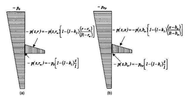
Figure 2. Distribution of vacuum pressure along PVD (a) axisymmetric; and (b) equivalent plane strain based on laboratory observations (Indraratna et al., 2005)
Based on the assumption of variations in the value of the k1 vertical pressure reduction factor and the k2 horizontal pressure reduction factor in Fig. 2, according to Indraratna (Indraratna et al., 2005) and Rujikiatkamjorn (Rujikiatkamjorn et al., 2007) there are 2 variations of the distribution of vacuum preloading in the simulation of finite element combination of vacuum pressure and PVD that are close to the actual measurement of the decrease and pore water pressure in the field, namely: first, uniform or constant vacuum pressure along both the PVD and the ground surface (k1 = k2 = 1 ) and second, uniform vacuum pressure at ground level (constant), but varies linearly to zero along the PVD (k1 = 0 and k2 = 1).
2.2 Horizontal strain due to vacuum pressure
The soil condition, when applied to vacuum pressure, is shown in Fig. 3. If the vacuum pressure is greater than the pressure required to maintain the soil in at-rest condition, lateral deformation will occur (Chai et al., 2005) of:
\[z_c = \frac{2c'}{\gamma_t \sqrt{K_a}}, for \ z_c < z_w \tag{1}\]
\[z_c = \frac{1}{(\gamma_t - \gamma_w)} \left( \frac{2c'}{\gamma_t \sqrt{K_a}} - \gamma_w z_w \right), for \ z_c > z_w\] (2)
Vertical strain caused by vacuum pressure is obtained by the equation:
\[\varepsilon_{vv} = \frac{\alpha \lambda}{1 - e} \ln \left( 1 + \frac{\Delta \sigma_{vac}}{\sigma'_{vo}} \right) \tag{3}\]
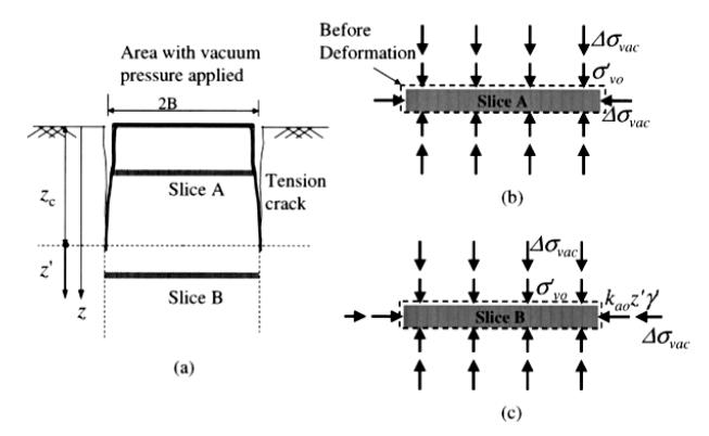
Figure 3. Deformation patterns and the state of tension in soils due to vacuum pressure (a) the location of the soil fragment; (b) above the tension crack; and (c) under tension crack (Chai et al., 2005).
For over consolidated soil, \(\lambda\) is changed to \(\kappa\). The \(\alpha\) value varies with depth, where on the ground surface meets the value of \(\alpha\)min= 0.85.
\[\alpha = \alpha_{min} + \frac{1 - \alpha_{min}}{\Delta \sigma_{vac}} \left( \frac{k_o \sigma'_{vo} - \sigma'_{av}}{1 - k_o} \right) \tag{4}\]
Volumetric strain is expressed in the equation:
\[\varepsilon_{vol} = \frac{\lambda}{1 - e} \ln \left( 1 + \frac{\Delta \sigma_{vac}}{\sigma'_{vo}} \right) \tag{5}\]
Horizontal strain and lateral deformation are expressed in the equation:
\[\varepsilon_h = \varepsilon_{vol} - \varepsilon_{vv} \delta_h = B\varepsilon_h\] (6)
where B is half the width of the soil improvement area.
2.3 PVD
In general, PVD installation is done in a square or triangle pattern. Furthermore, the axisymmetric unit cell theory was developed to simplify the problem of the consolidation phenomenon that occurs (Barron, 1948; Richart, 1957; and Hansbo, 1981).
The smear effect during the PVD installation process needs to be considered, especially related to the diameter parameters of the equivalent drainage cylinder (dw) and the radial permeability coefficient (kh). Table 1 shows the number of ds/dw and kh/ks ratio recommendations by several researchers.
In addition, an equivalent plane strain solution from radial consolidation that occurs along the PVD has also been proposed by Indraratna et al. (2005), as in Fig. 4.
3. Finite Element Modeling, Vaccum Preloading and PVD
3.1 Soil condition, vacuum pressure and PVD
In this finite element study, in general, soil conditions consisted of 3 layers of soil as listed in Table 2.
The parameters of the MCC soil model and the magnitude of the vertical and horizontal permeability equivalent plane strain for Clayey Silt are listed in Table 3.
Vacuum pressure was applied for 90 days with a tension of -80 kPa. There were two cases investigated in this study, first, uniform vacuum pressure at the ground surface (constant) but varied linearly to zero along the PVD (k1 = 0 and k2 = 1). Second, the vacuum pressure along both the PVD and the ground surface was constant (k1 = k2 = 1). While PVD was modeled along 18 m with 1.5 m space, mandrel
Tabel 1. ds/dw and kh/ks ratio recommendations (Bo et al., 2003)
| , | ||
|---|---|---|
| Researcher | ds/dw | kh/ks |
| Hansbo (1981,1997); Basu Prezzi, Madhav (2010) | 2 - 3 | 3 - 4 |
| Indraratna and Redana (1998) | 4 - 5 | 2 - 3 |
| Holtz and Holm (1972) | 2 times the effective mandrel diameter | - |
Figure 4. Unit cell analysis for axisymmetric and equivalent plane strains conditions (after Indraratna et al., 2005)
Table 2. Soil conditions depth, soil type
| Depth (m) | Soil Type | N - SPT | Su (kN/m2) | PI (%) | OCR |
|---|---|---|---|---|---|
| 0 - 18 | Clayey Silt | 4 | 24 | 26 | 1.7 |
| 18 - 29 | Clayey Silt | 33 | 203 | 26 | 7.3 |
| 29 - 30.5 | Silty Sand with Clay | 44 | 264 | 17 | 9.4 |
Table 3. MCC model parameters
| Material | Depth (m) | λ | κ | М | ν | Kvp (m/s) | Khp (m/s) | Ksp (m/s) |
|---|---|---|---|---|---|---|---|---|
| Clayey Silt 1 | 0 - 18 | 0.18 | 0.036 | 1.11 | 0.25 | 1.68.E-10 | 2.02.E-10 | 2.34E-10 |
| Clayey Silt 2 | 18 - 29 | 0.17 | 0.034 | 1.16 | 0.30 | 3.55.E-11 | 4.25.E-11 | 2.04L-10 |
dimensions of 120x60 mm2, and PVD dimensions of 100x5 mm2.
3.2 Numerical modeling
Numerical equivalent plane strain modeling was carried out using the Abaqus finite element program (Dassault Systemes Simulia Corp., 2014) that used the Biot consolidation theory. The finite element mesh used a CPE8RP (8-node biquadratic displacement, bilinear pore pressure) rectangular element as shown in Fig. 5.
Vacuum preloading was carried out in stages, the pump was started on day 0 and reached a pressure of - 80 kPa on the 15th day until it was then stable until the desired consolidation process was completed on the 90th day, as in Fig. 6.
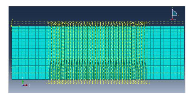
Fig. 5. Element types on abaqus and 2D meshing
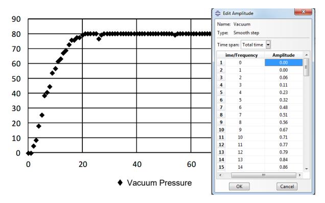
Figure. 6. Vacuum pressure (left: chart); (right: abaqus input).
Vacuum preloading was modeled using boundary condition tools. The boundary condition on the PVD element was given a negative pore pressure of -80 kPa with a pressure distribution varying to zero at the PVD end and uniform (constant) along the PVD.
3.3 Numerical modeling results
The soil settlement from finite element modeling using Abaqus is shown in Fig. 7. Next, a comparison with the results of the Terzaghi 1-D consolidation calculation is shown in Fig. 8.
Evaluation of the settlement that occurred as a result of the finite element method with constant vacuum pressure on the Terzaghi 1-D Consolidation calculation showed that the total consolidation
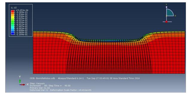
Figure. 7. Settlement of finite element method analysis result deformed mesh.

Figure. 8. Settlement resulted from terzaghi 1-D consolidation and finite element method comparison chart
decrease that occurred was relatively close by 17 cm and was relatively larger than the result of modeling with a distributed vacuum pressure of about 12 cm. However, the predicted settlement in consolidation until the 50th-day results of the distributed vacuum pressure was relatively close to the results of the Terzaghi 1-D consolidation calculation.
Evaluation of the lateral deformation that resulted from the prediction of the finite element method due to vacuum preloading compared to the land fill with load equivalence and its comparison with the analytical method prediction is shown in Fig. 9.
Negative lateral deformation indicates an outward soil movement as seen in preloading which has the potential to cause shear failure. Meanwhile, in vacuum
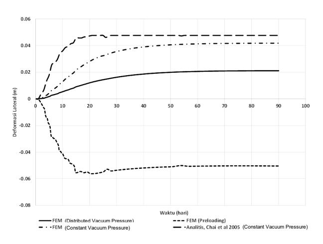
Figure. 9. Comparative chart of lateral deformation prediction of vacuum preloading and preloading from finite element method and analytical method results
preloading, a positive lateral movement indicates an inward soil movement.
4. Conclusions
In this paper, a finite element method analysis by considering the smear effect and equivalent plane strain was carried out to predict soil consolidation behavior due to vacuum preloading and PVD. Some important conclusions obtained from this study are:
- 1. The rate and magnitude of consolidation settlement that occurred resulted from the prediction of the finite element modeling with constant vacuum pressure along both PVD and the ground surface was relatively greater than a linearly distributed vacuum pressure to zero along the PVD. These results also confirmed the results obtained by Indraratna et al. (2005).
- 2. Comparison of the total consolidation settlement with a constant vacuum pressure along the PVD and the ground surface from finite element modeling prediction relatively close to the calculation of Terzaghi 1-D consolidation.
- 3. However, the finite element prediction of consolidation rate with a linearly distributed vacuum pressure to zero along the PVD was closer to the calculation results with the Terzaghi 1-D consolidation.
- 4. Finite element prediction of vacuum preloadinginduced lateral deformation indicated a positive soil movement (inward movement), so it might reduce the possibility of shear failure commonly occured in conventional preloading (outward soil movement).
The results and conclusions in this paper need to be continued by looking at the comparison with the actual measurements in the field.