
Abstrak
Modernisasi sistem observasi meteorologi di Badan Meteorologi, Klimatologi, dan Geofisika (BMKG) diperlukan, khususnya untuk parameter suhu tanah dan kadar air tanah yang masih umum diukur menggunakan metode konvensional. Penelitian ini menyajikan perancangan dan evaluasi sistem pemantauan berbasis Internet of Things (IoT) untuk meningkatkan efisiensi observasi. Sistem ini mengintegrasikan sensor PT100 untuk mengukur suhu tanah pada kedalaman 5, 10, 20, 50, dan 100 cm, serta sensor Capacitive Soil Moisture v2.0 untuk mengukur kadar air tanah volumetrik pada kedalaman 10, 20, 30, 50, dan 100 cm. Data pengukuran dikirimkan secara real-time melalui Wi-Fi ke Google Spreadsheet dan bot Telegram sehingga memungkinkan pemantauan jarak jauh dan notifikasi otomatis, serta disimpan secara lokal pada kartu SD untuk meningkatkan keandalan sistem. Kinerja sensor dievaluasi melalui kalibrasi laboratorium di dalam temperature chamber dan pengujian lapangan selama 11 hari di Kantor Pusat BMKG Wilayah II. Hasil evaluasi menunjukkan akurasi yang baik, dengan RMSE sebesar 0,93 °C (MAE 0,66 °C) pada kedalaman 5 cm dan RMSE sebesar 0,43 °C (MAE 0,29 °C) pada kedalaman 10 cm, yang menunjukkan bahwa sistem memiliki kinerja yang andal.
Kata Kunci: Internet of Things (IoT), suhu tanah, kadar air tanah, sistem monitoring, Telegram
Paper accepted February 1st 2026 – paper revised March 12th 2026 – approved April 9th 2026
This paper is open access with CC BY-SA license.
1 Introduction
The current technological advancements have enabled the creation of numerous tools that assist human activities and optimize time management more effectively [1]. One area of optimization is weather parameter observation. According to the Head of the Meteorology, Climatology, and Geophysics Agency (BMKG) Regulation Number 4 of 2016 [2] concerning Climate Data Observation and Management within BMKG, monitoring activities conducted by BMKG involve measuring values recorded by instruments placed in observation gardens. BMKG is responsible for providing information services related to weather, climate, and tectonic activities associated with earthquakes. Among the parameters observed by BMKG are soil temperature and soil moisture content.
Soil temperature is the result of total radiation, which is a combination of wavelength emissions from heat flow within the soil [3]. Soil moisture content is defined as the amount of water contained in the soil, often referred to as soil humidity [2]. Soil moisture measurement is essential for water resource management, early drought warning systems, weather forecasting data, and has been widely used in scientific and engineering fields [4]. Aside from numerical weather prediction, soil temperature is also a crucial factor for plant growth, playing a role in determining chemical reactions and microbial activity in soil that decompose certain organic compounds into nutrients. Both parameters are fundamental soil characteristics for maximizing plant growth and development, making soil temperature and moisture information vital for agricultural purposes [5]. Therefore, a soil temperature and moisture observation system is necessary to support plant growth and development.
Current soil temperature and moisture observation generally employs conventional equipment [6], with soil temperature readings taken using buried thermometers [2]. Soil temperature observation at several BMKG stations and offices still involves the use of mercury thermometers inserted into the soil. However, the use of such thermometers has been prohibited through the Minamata Convention in 2017 due to their hazardous content for human health and the environment [7]. In addition to containing hazardous materials, mercury thermometers are inefficient due to the risk of parallax errors in reading [8]. In response to the ban on mercury thermometers, the WMO strongly suggests replacing the use of such thermometers with modern alternatives as soon as possible. WMO suggests the use of electrical resistance thermometers such as PT100 as they provide an economical, accurate and reliable alternative to the dangerous mercury-based precedents and other significant advantages in terms of data storage and real-time display [9]. This sensor is used in this study as a soil temperature measurement device, based on research showing similar trends in reading actual temperature with high accuracy [10]. Similarly, soil moisture level measurement is still conducted through sensor readings monitored via computer programs, limiting observations to computer displays and making data difficult to access remotely. To improve soil moisture parameter monitoring, this study employs the Capacitive Soil Moisture Sensor v2.0, which offers a simple, practical, and efficient structure. This sensor has demonstrated effective performance and is suitable for building large-scale agricultural wireless sensor networks while being a cost-effective and reliable solution compared to expensive commercial soil moisture devices [11][12].
The transition from conventional to automated observation requires further research due to numerous challenges such as compatibility with historical data, observation accuracy, and measurement validation [13][14][15]. Despite these challenges, several studies have been conducted to facilitate the observation of these parameters. IoT-based soil moisture monitoring systems have been explored, transmitting sensor data through internet platforms such as ThingSpeak to enable remote smartphone access; however, this approach is limited to single-surface monitoring and focuses primarily on system performance rather than comprehensive data acquisition [16]. Similarly, radio communication-based systems utilizing SHT11 sensors with ATMEGA2560 microcontrollers have been developed, though they remain constrained to surface-level soil water content measurement with data display restricted to a PC interface [6]. Building upon these efforts, more advanced monitoring systems incorporating DS18B20 temperature sensors, YL-69 moisture sensors, and ESP32 microcontrollers have been implemented alongside IoT platforms such as Thinger.io for real-time visualization; yet these systems still operate at a single surface level and do not address the multi-depth measurement standards specified by BMKG [17]. A closer step toward multi-depth monitoring was achieved through digitalization efforts employing thermocouple sensors at various soil depths with ATMega16 microcontrollers and LabVIEW interfaces, although accessibility remains limited to PC-based display only [18].
These studies have implemented the Internet of Things (IoT) concept, which enables devices to interact with each other using the internet, creating smart systems applicable across various fields such as entertainment and transportation [19][20]. The IoT concept not only facilitates the replacement of mercury thermometers with sensor-based systems but also enables remote monitoring for weather observers and agricultural purposes [21]. In response to these needs, this study designs and builds a remote monitoring system for soil temperature and moisture based on the Internet of Things. The system utilizes an ESP32 microcontroller, along with a Telegram bot and Google Spreadsheet for displaying measured data. This system is expected to enable BMKG personnel to remotely read soil temperature and moisture parameters via smartphones or PCs, facilitating data compilation on the BMKGsoft website for further processing by relevant stakeholders.
2 Method
This chapter presents the overall system design concept in detail, consisting of the system block diagram, the system's flowchart, hardware schematic, software design and the calibrations of the sensors used in the study.
https://doi.org/10.5614/joki.2026.18.1.10 E-ISSN: 2460-6340
2.1 System Block Diagram
Figure 1 presents the block diagram of the proposed system for measuring and recording soil temperature and moisture content. The system comprises three main sections: input, processing, and output.
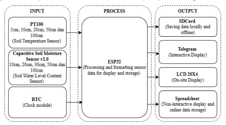
Figure 1. System block diagram
The input section consists of five PT100 soil temperature sensors, five Capacitive Soil Moisture v2.0 sensors for measuring volumetric soil water content, and a Real-Time Clock (RTC) module. As shown in Figure 1, the PT100 sensors measure soil temperature at various depths, while the soil moisture sensors determine soil water content, and the RTC provides accurate timestamps for each measurement. These inputs are connected to a NodeMCU ESP32 microcontroller in the processing section, which collects the sensor readings, attaches timestamps, and prepares the data for storage and display. The output section distributes the processed data through several channels: a 20×4 LCD for offline display, a Telegram bot for interactive remote access, Google Sheets for online visualization and storage, and a microSD card for local backup to ensure data reliability during network interruptions.
2.2 System Flowchart
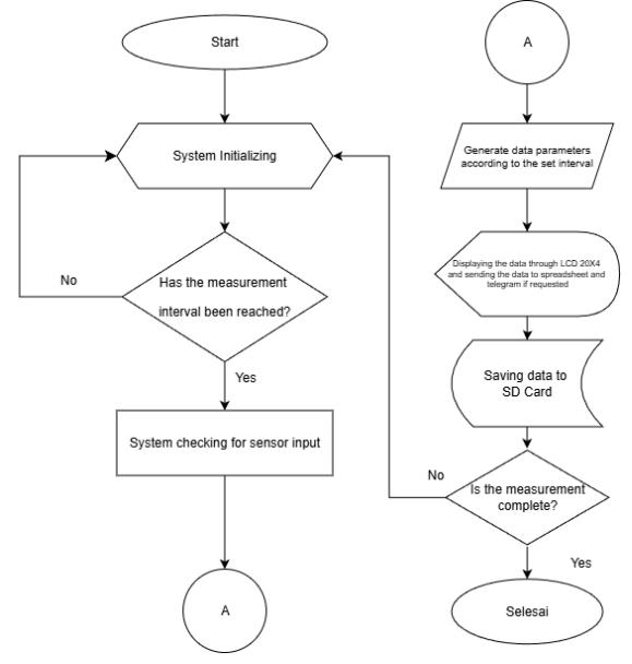
Figure 2 System flowchart
The operational flow of the proposed system is illustrated in Figure 2. Upon startup, the system initializes the Real-Time Clock (RTC), ESP32 microcontroller, and sensors. At each predefined interval, the system collects sensor readings and generates timestamped data records. The data is displayed locally on a 20×4 LCD, alternating between soil temperature and soil moisture every 5 seconds. The ESP32 maintains a Wi-Fi connection to enable remote interaction through a Telegram bot, allowing users to request the latest data. Measurements are logged every 10 minutes and stored both locally on a microSD card and remotely in Google Sheets to ensure data redundancy and accessibility. The system operates continuously for 24 hours and automatically transmits soil temperature and soil moisture data at scheduled times in accordance with BMKG Regulation No. 4 of 2016.. Overall, the system designed in this study aims to modernize soil temperature and soil water level content monitoring using the IoT approach.
Jurnal Otomasi Kontrol dan Instrumentasi Vol18 (1), 2026 ISSN: 2085-2517 https://doi.org/10.5614/joki.2026.18.1.10 E-ISSN: 2460-6340
2.3 System Schematic Diagram
The circuit schematic diagram is designed to facilitate the planning and arrangement of the components that the system is going to use. The diagram can be seen in Figure 3.
Figure 3. System schematic diagram
Through this schematic, each connection between components can be clearly visualized, helping to ensure an organized design and minimizing errors during the assembly process. Moreover, the schematic serves as an essential guide during testing and troubleshooting, as each electrical connection path can be easily traced. The components used in this system include a solar cell, ESP32, PT 100 sensors and its acquisition module, capacitive soil moisture sensors, LCD, Real-Time Clock (RTC), and SD card module.
The PT100 is an analog sensor; therefore, to produce a digital output, an analog-to-digital converter (ADC) or a dedicated module is required. In this research, the selected module is the PT100 Acquisition Module PTA9B01 (RS485 Modbus RTU). As its name implies, this module employs RS485 communication and the Modbus protocol. It enables data transmission from the PT100 sensor to the ESP32 via RS485, interfaced through a MAX485 transceiver. The module operates on a 12 V power supply, drawing power directly from a mains AC adapter, while its operational requirements include a 5 V supply for certain components. This module utilizes the Modbus communication protocol, a master-slave data exchange standard in which each slave device must have a unique address to prevent conflicts in data request and response traffic. The pin configuration for this module is described in Table 1.
No. Components Components pin Acquisition module pin 1. PT100 Red Wire P+ Blue Wire 1 P-Blue Wire 2 GND
Table 1. PT100 acquisition module pin configuration
The MAX485 is a low-power transceiver IC designed for RS-485/RS-422 communication, operating from a single 5V supply. It features one driver and one receiver, supporting half-duplex communication with data rates up to 2.5 Mbps. In this study, the MAX485 acts as the communication bridge between the PT100 Acquisition Module and the ESP32 microcontroller. Specifically, it converts the ESP32's TTL logic levels (typically 3.3V or 5V) to differential RS485 signals. The pin configuration for MAX485 can be seen in Table 2.
https://doi.org/10.5614/joki.2026.18.1.10 E-ISSN: 2460-6340
Table 2. MAX485 configuration pin
| No. | Components | Components pin | MAX485 pin |
|---|---|---|---|
| 1. | PT100 Acquisition Module | VCC | VCC |
| (PTA9B01) | GND | GND | |
| A+ | A | ||
| B- | B |
Since certain components require a 12 V power supply while others operate at 5 V, the system employs a 12 V mains adapter as the primary power source. This adapter directly supplies the PT100 Acquisition Module, whereas components necessitating 5 V—including the ESP32 microcontroller, the LCD display, and the MAX485 transceiver—are powered through a step-down voltage regulator module. The configuration for the step down module can be seen in Table 3.
Table 3. Step down module pin configuration
| No. | Components | Components pin | Step down module pin |
|---|---|---|---|
| 1. | LCD | VCC | OUT+ |
| GND | OUT | ||
| 2. | ESP32 | VIN | OUT+ |
| GND | OUT | ||
| 3. | MAX485 | VCC | OUT+ |
| GND | OUT |
2.4 Hardware Design
The hardware design visualizes how the circuit system would be employed in a casing. The casing design was produced using SketchUp allowing an easier visualization and serves as a guide before manufacturing the physical prototype. The design can be seen in figure 4.
Figure 4. Hardware design
The logger enclosure has external dimensions of 30 cm × 22 cm × 12 cm. Ports are provided on the bottom face of the enclosure to allow entry of the temperature sensor and soil moisture sensor cables into the microcontroller. An additional port is on the right side to accommodate the system power supply cable. The front face of the enclosure features a 20×4 LCD display for presenting the measured parameters. The logger enclosure is positioned close to the soil sample under measurement, as depicted in Figure 5.
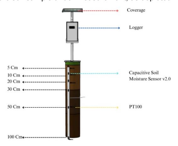
Figure 5. System implementation plan
Jurnal Otomasi Kontrol dan Instrumentasi Vol18 (1), 2026 ISSN: 2085-2517 https://doi.org/10.5614/joki.2026.18.1.10 E-ISSN: 2460-6340
2.5 Software Design
The software design in this study consists of programming for the microcontroller and configuring the Telegram bot using the Arduino IDE.
2.5.1 Microcontroller Program
Programming on the ESP32 was carried out using the Arduino IDE. The program was developed to connect all components, establish a Wi-Fi connection, generate each parameter measurement with timestamp, store the data to an SD card, and display it on an LCD. Furthermore, the program manages all available bot commands and sends automatic notifications via the Telegram bot.
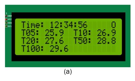
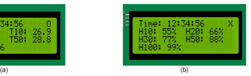
Figure 6. LCD display design (a) Soil temperature (b) Soil water content
As illustrated in Figure 6, one key aspect of the ESP32 programming involves the configuration of the LCD display. The 20×4 LCD is designed to present real-time information as follows: the first row displays the current time along with a Wi-Fi connection indicator ("X" for disconnected and "O" for connected). The second through fourth rows show the measured parameters, where "T" denotes soil temperature and "H" represents soil water content. The numerical value following each symbol indicates the measurement depth in centimeters (e.g., T10 corresponds to soil temperature at a 10 cm depth). Additionally, the display alternates between showing soil temperature and soil water content values every 5 seconds to provide a comprehensive overview without requiring manual intervention.seconds.
2.5.2 Telegram Bot Program
The Telegram bot is designed to incorporate three primary features to facilitate remote monitoring of soil temperature and moisture levels. These include: (1) automatic notifications sent at each scheduled measurement interval for the respective parameters; (2) manual data requests to retrieve real-time readings outside the predefined observation schedule, enabling verification of device and sensor operational status; and (3) retrieval of historical measurement data corresponding to scheduled observation times, which is particularly useful for accessing offline-stored data when automatic notifications are disabled. Figure 7 shows the initial telegram bot display.
Figure 7. Telegram bot display
2.6 Sensor Calibration
The calibration of the sensors was conducted to evaluate the extent to which the sensors employed in this system perform optimally in terms of performance, accuracy, stability, and reliability.
2.6.1 PT 100 Calibration
The comparison was performed by comparing the readings of the PT100 sensors against those of a standard Fluke Hart 5627 temperature probe within a Temperature Test Chamber (Theodor Friedrichs & Co.) conducted at BBMKG Wilayah II on May 28th 2025. The calibration process involved placing each of the five PT100 sensors alongside the standard probe inside the chamber as seen in Figure 8. The comparison was conducted at three temperature set points: 20 °C, 30 °C, and 40 °C. Once the chamber temperature had stabilized at each set point, five consecutive readings were taken for both the PT100 sensors and the standard probe.
Figure 8. PT100 calibration process
The calibration results were averaged across the five readings at each temperature set point. Subsequently, the correction values obtained from the three set points (20 °C, 30 °C, and 40 °C) were averaged to determine the final offset value. This offset was then applied to the PT100 sensors through the ESP32 program to improve measurement accuracy. The results for each sensors are as follow :
• First PT100 : 0.21 o C • Second PT100 : 0.077 o • Third PT100 : 0.197 o C • Fourth PT100 : 0.39 o C • Fifth PT 100 : -0.283 o C
Following the completion of the comparison process for all sensors, the average correction values obtained from the five PT100 sensors were incorporated into the Arduino IDE sketch as offset values to compensate for systematic errors and enhance overall measurement accuracy.
2.6.2 Capacitive Soil Moisture Sensor V2.0 Validation
C
The testing of the soil moisture sensors was carried out by conditioning the measurement medium under three distinct scenarios: (1) the sensor placed in dry soil (prior to watering), (2) the sensor placed in watered soil, and (3) the sensor exposed to air (removed from the soil). The objective of this validation test was to assess whether the sensors accurately reflected changes in soil moisture corresponding to the applied conditions. For each conditioning scenario, measurements were performed 10 times, and the values were recorded to observe any consistent variations across the tested conditions. The results of this testing are presented in Table 4.
Table 4. Capacitive soil moisture sensor v2.0 validation
| Treatment | Reading no. | Sensor 1 | Sensor 2 | Sensor 3 | Sensor 4 | Sensor 5 |
|---|---|---|---|---|---|---|
| 1 | 1% | 5% | 0% | 0% | 2% | |
| 2 | 1% | 6% | 0% | 0% | 2% | |
| 3 | 1% | 6% | 0% | 0% | 2% | |
| 4 | 1% | 5% | 0% | 0% | 2% | |
| Dry Soil | 5 | 1% | 6% | 0% | 0% | 2% |
| 6 | 1% | 6% | 0% | 0% | 1% | |
| 7 | 1% | 5% | 0% | 0% | 1% | |
| 8 | 1% | 6% | 0% | 0% | 1% | |
| 9 | 2% | 6% | 0% | 0% | 1% | |
| 10 | 1% | 5% | 0% | 0% | 1% |
https://doi.org/10.5614/joki.2026.18.1.10 E-ISSN: 2460-6340
Table 4. (continued)
| Treatment | Reading no. | Sensor 1 | Sensor 2 | Sensor 3 | Sensor 4 | Sensor 5 |
|---|---|---|---|---|---|---|
| 1 | 100% | 100% | 100% | 100% | 100% | |
| 2 | 100% | 100% | 100% | 100% | 100% | |
| 3 | 100% | 100% | 100% | 100% | 100% | |
| 4 | 100% | 100% | 100% | 100% | 100% | |
| Poured 235ml | 5 | 100% | 100% | 100% | 100% | 100% |
| water | 6 | 100% | 100% | 100% | 100% | 100% |
| 7 | 100% | 100% | 100% | 100% | 100% | |
| 8 | 100% | 100% | 100% | 100% | 100% | |
| 9 | 100% | 100% | 100% | 100% | 100% | |
| 10 | 100% | 100% | 100% | 100% | 100% | |
| 1 | 0% | 0% | 0% | 0% | 0% | |
| 2 | 0% | 0% | 0% | 0% | 0% | |
| 3 | 0% | 0% | 0% | 0% | 0% | |
| 4 | 0% | 0% | 0% | 1% | 1% | |
| 5 | 0% | 0% | 0% | 0% | 1% | |
| Outside of soil | 6 | 0% | 0% | 0% | 0% | 0% |
| 7 | 0% | 0% | 0% | 1% | 1% | |
| 8 | 0% | 0% | 0% | 0% | 0% | |
| 9 | 0% | 0% | 0% | 0% | 0% | |
| 10 | 0% | 0% | 0% | 0% | 0% |
All five sensors exhibited consistent measurements across each treatment, leading to the conclusion that the sensors are reliable and ready for use in accordance with the objectives of this research.
3 Results and Discussion
This chapter discusses the implementation of the designed system as outlined in the preceding chapters. It includes the realization of both hardware and software components, as well as the outcomes of field testing related to soil temperature and soil water content recordings.
3.1 Hardware Design Implementation
The hardware used in this study consists of a microcontroller, PT100 Sensors, RTC, SD card module, Capacitive soil moisture sensors and other supporting components. The components were connected using jumper cable on a project board. As shown in Figure 9.
The assembled components were then securely placed inside a waterproof and weatherproof enclosure, enabling safe outdoor operational testing. The logger enclosure was subsequently mounted on a support pole with a height of 80 cm above the ground. At the top of the pole, a dedicated roof mount was installed to accommodate a rectangular acrylic solar panel measuring 40 cm × 30 cm. The sensors were deployed into a 100 cm deep borehole lined with a PVC pipe, with holes precisely drilled at the designated depths to allow accurate placement of each sensor according to its intended measurement depth. The implementation of the pole and sensor deployment can be seen in Figure 10.
Figure 9. Hardware implementation
Figure 10. Sensor deployment
3.2 Software Implementation
In this study, the software implementation involves the development and integration of three main components: the LCD display interface, the Telegram bot for remote monitoring, and data logging functionality utilizing both an SD card (for local offline storage) and Google Spreadsheet (for cloud-based real-time and historical data access).
3.2.1 LCD Display
The 20×4 LCD display implemented in this system follows the designed layout. The first row shows the current timestamp in the format Hour:Minute:Second (HH:MM:SS) on the left side, with a Wi-Fi connection indicator positioned at the far right ("O" for connected and "X" for disconnected). Rows two through four are dedicated to displaying the measured soil temperature and soil moisture content at the specified depths. The LCD is programmed to automatically alternate between displaying soil temperature and soil moisture data every five seconds, ensuring users can view both parameters without manual intervention. The LCD implementation can be seen in Figure 11.
Figure 11. LCD display on-field implementation
3.2.2 Telegram Bot
The second implementation is the telegram bot, which serves as a remote interactive display and communication interface with the system. The implementation can be seen in Figure 12 as it showcases the request recent data feature and request historical data works as it is designed.
Figure 12. Telegram bot implementation
3.2.3 Data Storage
The system is designed to periodically record measurement data in two file formats—CSV and TXT—stored on a MicroSD card as the storage medium. The recorded data include the measurement timestamp, soil temperature values at each designated depth, and soil moisture content at the specified depths, with logging performed every 10 minutes.
The CSV format was selected due to its structured layout, which facilitates straightforward processing and analysis using software such as Microsoft Excel or Google Sheets. This makes it particularly suitable for rapid technical data analysis and visualization. Meanwhile, the TXT format was chosen for its lightweight nature, ease of direct human readability, and broad compatibility with various text-based data processing systems. It also serves as a reliable backup of raw data that can be readily accessed by other systems without requiring format conversion.
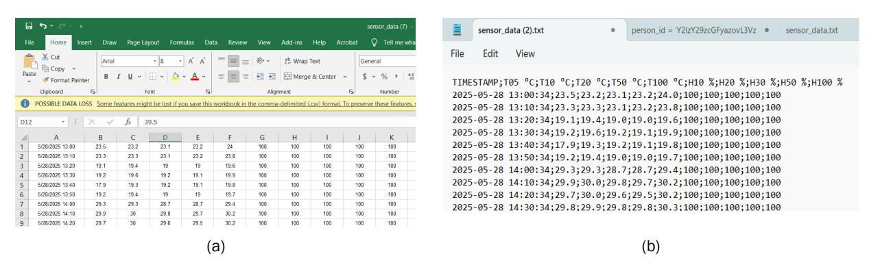
Figure 13. Data Storage Implementation, (a) csv format (b) txt format
As depicted in Figure 13 the data stored in the .csv and .txt file is structured as the following timestamp data, the parameter data in each depth, saved every 10 minutes. Both formats contain the same data where the only difference is .csv separates each value in commas, facilitating easier processing and analysis.
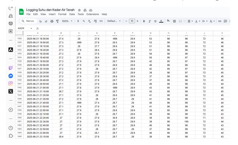
Figure 14. Spreadsheet display and implementation
In addition to offline data storage, this system is also designed with an online-accessible overall data visualization feature in the form of a spreadsheet. Figure 14 illustrates the spreadsheet interface and the recorded data. The layout is identical to the content of the CSV file, with the header row at the top containing the title of each column. Graphics figures should not have grids, show only horizontal and vertical axes.
3.3 Results and Evaluation
The testing of the designed instrument was conducted over a period of 11 days, from 18 June to 30 June 2025. Since the system is designed to operate using PLN (state electricity) power, the selected location provided a significant advantage: the availability of power outlets for electricity supply. In addition, the presence of PLN power infrastructure within the instrument park further ensured reliable and continuous operation. The overall data measured is summarized in the following Table.
Table 5. Overall data of the measured parameter
| Data | |||
|---|---|---|---|
| Parameter | Mean | Max | Min |
| T05 °C | 27.8593 | 30.6 | 26.3 |
| T10 °C | 28.3758 | 29.9 | 27.3 |
| T20 °C | 28.3172 | 29 | 27.5 |
| T50 °C | 28.888 | 29.5 | 28.3 |
| T100 °C | 29.1493 | 30 | 28.8 |
| H10 % | 16.2823 | 88 | 0 |
| H20 % | 93.5203 | 100 | 78 |
| H30 % | 84.2502 | 100 | 50 |
| H50 % | 72.0508 | 90 | 65 |
| H100 % | 32.0669 | 62 | 18 |
Initially, the study was planned to collect data at the Stasiun Klimatologi Banten, which would have allowed for a comprehensive comparison of all observed parameters. However, due to unforeseen obstacles—specifically, the unavailability of their operational instruments—the data collection and testing were relocated to Balai BMKG Wilayah II. As a result, the comparison was limited to soil temperature measurements at depths of 5 cm and 10 cm.
Data collection was performed from 18 June 2025 at 18:50:00 to 30 June 2025 at 17:30:00, resulting in a total of 1,556 data rows retrieved from both the spreadsheet and the SD card. The stored data were subsequently normalized due to the presence of outliers caused by aliasing, primarily resulting from the delayed response time of the temperature sensor. Normalization was carried out by identifying outlier values or data points exhibiting extreme changes compared to the preceding measurement, and replacing them with the average of the values immediately before and after the outlier (i.e., the sum of the previous and subsequent data points divided by two).
3.3.1 Soil Temperature
Soil temperature measurements at various depths as seen in Figure 15 reveals a clear pattern: the deeper the soil layer, the more stable the temperature. At 5 cm depth, temperatures are most fluctuating (26.4°C– 30.6°C) due to strong diurnal surface temperature variations and weather conditions. At 10 cm, fluctuations become more moderate (27.3°C–29.9°C), while at 20 cm the pattern is even more stable (27.5°C–29.0°C). At 50 cm depth, the temperature range narrows further (28.3°C–29.5°C) with no extreme spikes observed. The deepest layer at 100 cm records the most stable conditions (28.9°C– 29.3°C), although a temporary anomaly reaching 30.0°C was noted, likely attributed to subsurface thermal variability or sensor measurement artifacts.
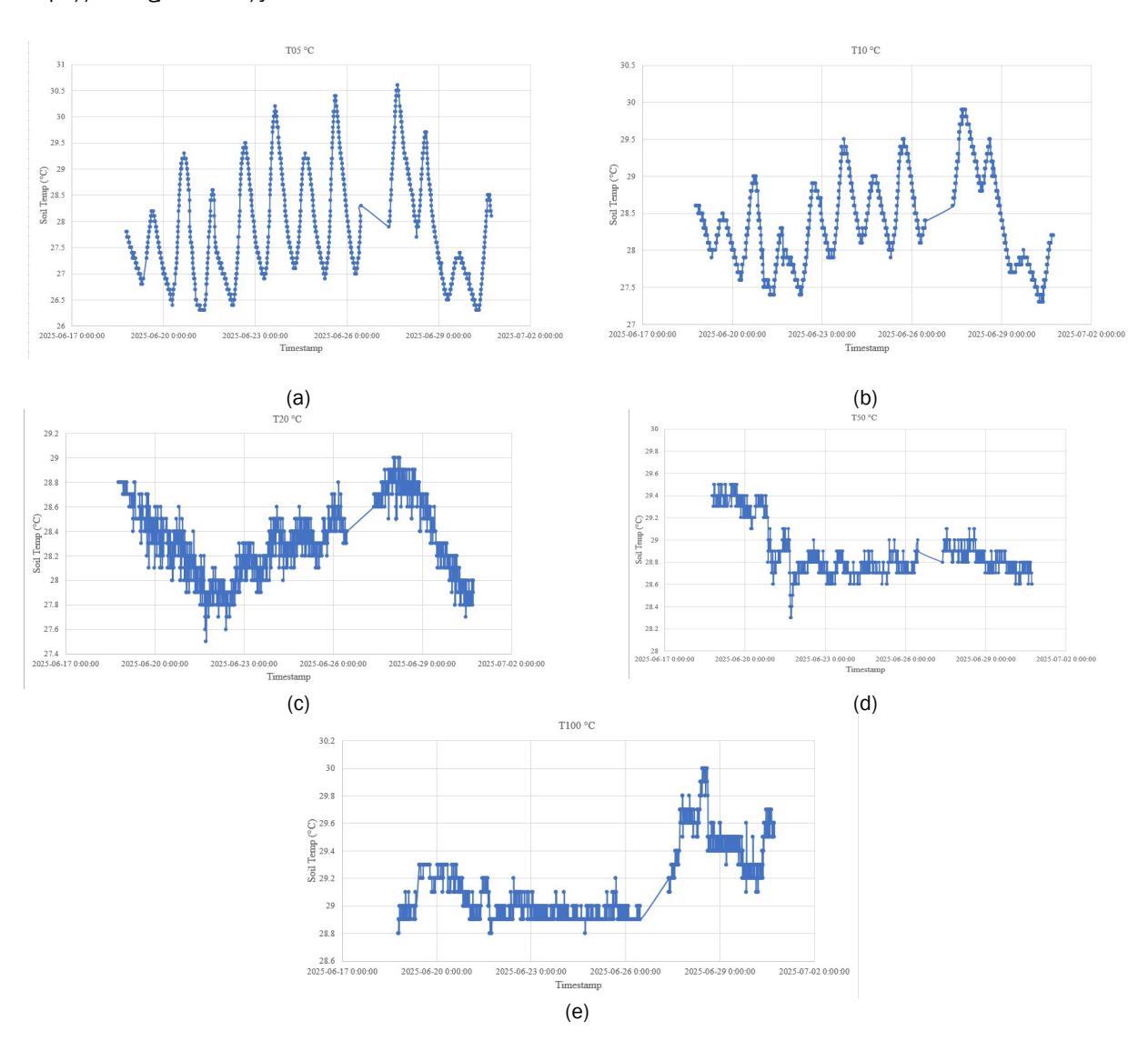
Figure 15. Soil temperature measurement trend, (a) 5cm depth, (b) 10 cm depth, (c) 20 cm depth, (d) 50 cm depth, (e) 100 cm depth
3.3.2 Soil Water Content
Soil water content measurements across different depths as seen in Figure 16 reveal varying patterns of stability and sensitivity. At 10 cm depth, moisture is highly fluctuative, ranging widely from 5% to 88%, reflecting strong sensitivity to surface-related factors. At 20 cm, the pattern becomes more stable, with moisture consistently maintained between 90% and 100% after an initial increase, indicating a strong moisture retention capacity at this layer.
At 30 cm depth, moisture ranges from 50% to 100%, with a decline observed only toward the end of the observation period, likely due to the absence of rainfall and downward percolation. This layer shows relatively less influence from surface conditions. The subsequent depth displays a highly consistent trend with values between 65% and 90%, suggesting greater isolation from direct surface influences.
At the deepest observed layer of 100 cm, moisture exhibits relatively fluctuative behavior ranging from 18% to 62%. This variability may be attributed to limited moisture retention capacity, vertical water movement from shallower layers following rainfall, or potential measurement artifacts resulting from suboptimal sensor placement.

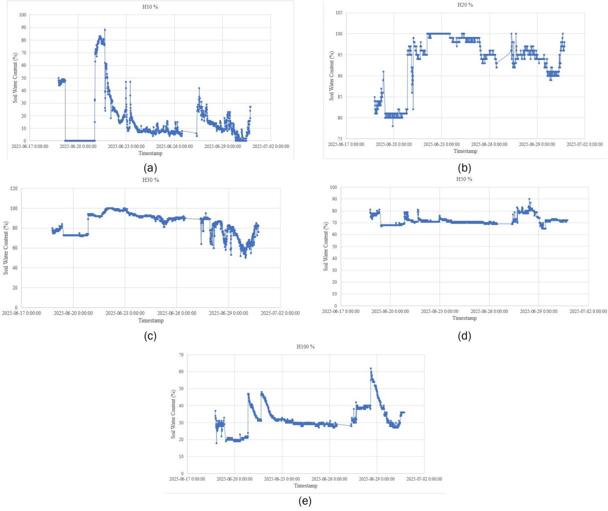
Figure 16. Soil water content measurement trend (a) 10 cm depth, (b) 20 cm depth, (c) 30 cm depth, (d) 50 cm depth, (e) 100 cm depth
Table 6. Rainfall data during the observation period
| H1 | H2 | Precipitation | Evaporation | |
|---|---|---|---|---|
| Date | (mm) | (mm) | (p) | p – (H1 - H2) |
| 18 | 28.5 | /// | 119.5 | /// |
| 19 | 32.9 | 44.6 | 14.2 | 2.5 |
| 20 | 40 | 40 | 0 | 0 |
| 21 | 40 | 74.4 | 39.5 | 5.1 |
| 22 | 32.0 | 46.0 | 17.5 | 3.5 |
| 23 | 46.0 | 50.7 | 9.5 | 4.8 |
| 24 | 50.7 | 48.3 | 0.5 | 2.9 |
| 25 | 48.3 | 45.4 | 0.1 | 3.0 |
| 26 | 45.4 | 41.5 | 0.5 | 4.4 |
| 27 | 41.5 | 37.7 | 0.0 | 3.8 |
| 28 | 37.7 | 35.0 | 0.0 | 2.7 |
| 29 | 35.0 | 44.1 | 12.7 | 3.6 |
| 30 | 44.1 | 45.0 | 1.7 | 0.8 |
The observed variation in soil water content across different depths is closely associated with the rainfall pattern recorded during the observation period in Table 6. The rainfall data from Table indicate significant temporal fluctuations, including a high-intensity precipitation event on day 18 with a recorded value of 119.5 mm, followed by subsequent days characterized by moderate to low rainfall. This rainfall pattern directly contributes to changes in soil moisture, particularly within the shallow soil layers.
In shallow depths, increased rainfall induces a rapid and highly fluctuative soil water content response, reflecting the strong sensitivity of these layers to surface water input. Sharp increases in soil moisture are observed following rainfall events, followed by relatively rapid declines during periods of reduced or absent precipitation. In contrast, soil moisture response at deeper layers tends to be slower and more stable. Rainwater infiltrates the soil profile and undergoes percolation processes, resulting in dampened moisture fluctuations at intermediate and deeper depths.
3.3.3 Soil Temperature Evaluation
An evaluation of the measurement results was conducted to assess the precision of the designed system in comparison with operational instruments used by BMKG. The evaluation was performed by comparing measurement results for the same parameters and observation times, followed by the calculation of the Root Mean Square Error (RMSE) and Mean Absolute Error (MAE) to quantify sensor reading errors. Due to field testing limitations, soil temperature measurements were only available at depths of 0, 2, 5, 10, and 30 cm, as soil thermometers for depths of 20, 50, and 100 cm were damaged. In addition, soil water content observations were not conducted as it was a designed measurement for climatology station that was unavailable for testing at the time. Therefore, the evaluation was limited to soil temperature measurements at depths of 5 cm and 10 cm, corresponding to the standard BMKG observation times of 07:30, 13:30, and 17:30.
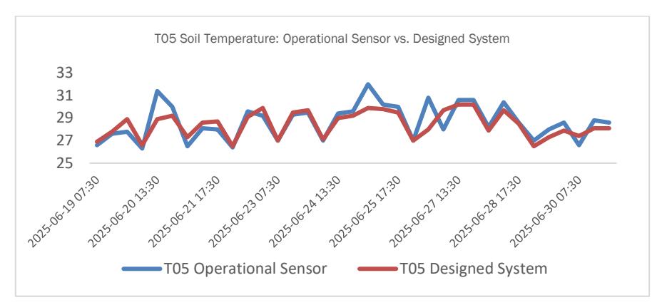
Figure 17. Soil temperature measurement comparison at 5 cm depth of the designed system vs operational sensor
Figure 17 presents a comparison of soil temperature between the operational measurements and those obtained from the designed system. As observed in the graph, both data series exhibit a closely aligned trend throughout the measurement period, with the T05 Operational Sensor and the T05 Designed System tracing nearly identical fluctuation patterns across all recorded timestamps from June 19 to June 30, 2025. The temperature values of both systems consistently fall within a narrow range of approximately 25°C to 33°C, and the two lines move in close synchrony — rising and falling together at nearly every data point. This visual agreement between the two curves suggests that the designed system is capable of capturing the dynamic behavior of soil temperature in a manner that closely mirrors the reference instrument. Minor deviations are visible at certain peaks and troughs, particularly around June 20 and June 25, where slight discrepancies in amplitude can be observed, yet the overall shape and direction of both signals remain highly consistent. Based on this comparison, the Root Mean Square Error (RMSE) was calculated to evaluate the measurement accuracy of the designed instrument. The RMSE value of 0.925 indicates that the T05 measurement system exhibits a reasonably good level of accuracy in capturing the observed parameter. In addition, the Mean Absolute Error (MAE) obtained from the measurement comparison is 0.66.
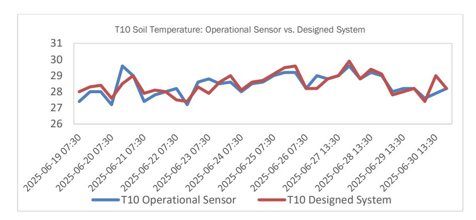
Figure 18. Soil temperature measurement at 10 cm depth comparison of the designed system vs operational sensor
Figure 18 presents a comparison of soil temperature measurements at a depth of 10 cm between the BMKG operational instrument and the designed system. As observed in the graph, both the T10 Operational Sensor and the T10 Designed System demonstrate a remarkably close agreement throughout the entire observation period spanning from late June 2025. The two lines follow nearly identical oscillation patterns, consistently fluctuating within a temperature range of approximately 26°C to 31°C, and exhibit a strong degree of synchrony in both the timing and magnitude of their rises and falls. Unlike the T05 comparison where occasional amplitude discrepancies were more noticeable, the T10 graph shows an even tighter overlap between the two curves across most of the recorded timestamps, with the red and blue lines frequently intersecting and tracking one another with minimal separation. Minor divergences are occasionally visible, particularly during certain peak periods where the designed system appears to slightly lead or lag the operational sensor by a small margin, yet the general trend and directionality of both signals remain highly consistent throughout. This visual closeness strongly indicates that the designed system is well-calibrated for the 10 cm depth soil temperature environment. Similar to the T05 evaluation, the T10 dataset was processed to obtain the Root Mean Square Error (RMSE) as an indicator of measurement accuracy. The calculated RMSE for the T10 parameter is 0.43 °C, indicating that the T10 measurement system exhibits very good accuracy and outperforms the T05 parameter, which recorded an RMSE of 0.925 °C. The lower RMSE value implies that the average deviation between the designed system and the operational reference instrument is approximately 0.43 °C, representing a significant improvement in measurement accuracy.
The Mean Absolute Error (MAE) for the T10 measurements is 0.29 °C, indicating that the average absolute difference between the designed system and the reference instrument is only about 0.29 °C. The MAE value being lower than the RMSE suggests that most measurement data points closely align with the reference values, with only a limited number of extreme deviations. Considering that the T10 measurement range varies from 26.8 °C to 32.0 °C, an average error between 0.29 °C and 0.43 °C reflects a high level of precision. Therefore, the designed system can be considered suitable for soil temperature monitoring in small- to medium-scale operational applications.
The observed differences between the operational instrument and the designed system may be attributed to variations in measurement conditioning methods. The operational instrument, which employs a mercury thermometer, generally does not maintain direct contact with the soil, whereas the PT100 sensor used in the designed system is directly embedded in the soil. This difference in contact medium may influence the measurement results. Additionally, discrepancies may arise from sensor quality, as the PT100 sensor implemented in the designed system may not achieve the same level of precision as the operational instrument. PT100 sensors are classified into Class A and Class B, where Class A sensors are intended for laboratory applications with lower error tolerance, while Class B sensors are designed for general-purpose use with higher permissible error. According to WMO No. 8, a PT100 sensor is classified as Class B if its measurement error falls within the tolerance range of ±(0.3 + 0.005|t|), which corresponds to approximately ±0.4 °C at a temperature of 20 °C.
Based on the evaluation results, the T10 sensor exhibits an average error of 0.29 °C, which remains within the specified tolerance range. This indicates that the sensor used for measurements at a depth of 10 cm satisfies the requirements for general-purpose applications in accordance with WMO No. 8. In contrast, the T05 sensor shows an average error of 0.66 °C, exceeding the allowable tolerance limit. Consequently, further calibration or sensor replacement is required for the 5 cm depth measurement to meet operational observation standards. Overall, while the system has been successfully designed and operates as intended, improvements in sensor selection or calibration—particularly for shallow-depth measurements—are necessary to ensure compliance with the accuracy standards specified by WMO No. 8. The developed monitoring system facilitates
the acquisition and processing of soil temperature and soil moisture data by integrating multiple sensors with an Internet of Things (IoT) platform. Using PT100 sensors and capacitive soil moisture sensors installed at several soil depths, the system enables continuous and simultaneous measurement of both parameters. According to the World Meteorological Organization (WMO), soil temperature observations are essential for understanding land–atmosphere energy exchange processes, supporting agrometeorological applications, and providing important inputs for land surface and climate models. Meanwhile, soil moisture observations play a crucial role in the hydrological cycle, influencing infiltration, runoff, evapotranspiration, and energy partitioning at the land surface. This automated approach improves the efficiency of data collection and enhances the availability of reliable soil temperature and soil moisture data for meteorological and environmental analysis.
4 Conclusion
The implementation and field testing results demonstrate that the proposed IoT-based soil temperature and moisture monitoring system has been successfully designed and is capable of performing its intended functions. The system effectively measures, records, and presents environmental data in real time through a dual-interface approach, consisting of an on-site display using a 20×4 LCD and remote access via a Telegram bot and Google Spreadsheet. This configuration enables both local and remote monitoring, while the data transmission process operates reliably under stable network conditions, indicating the system's potential for modern operational monitoring applications. The accuracy evaluation of soil temperature measurements shows encouraging results. At a depth of 5 cm, the system achieved an RMSE of 0.925°C and an MAE of 0.66°C, while at a depth of 10 cm, the RMSE and MAE values improved to 0.43°C and 0.29°C, respectively. These results indicate that the system provides measurements that are reasonably close to the reference operational instruments, particularly at deeper measurement depths. Nevertheless, the observed discrepancies suggest that further improvements are required, especially in terms of sensor selection and calibration, to achieve higher accuracy and meet stricter operational standards. To enhance overall system performance, several developments are recommended for future work. The use of a custom printed circuit board (PCB) is proposed to improve component integration and ensure more reliable electrical connectivity. In addition, future evaluations should be conducted in a more comprehensive testing environment, with more complete and comparable reference data, allowing the system's performance to be assessed under conditions that are directly comparable to operational standards. These improvements are expected to increase system reliability and support its application in small- to medium-scale operational soil monitoring systems.