
I. INTRODUCTION
Indonesia, renowned for its vast archipelago of over 18,000 islands, showcases an array of diverse maritime landscapes. However, this extensive island network presents a pressing issue that demands immediate attention: the necessity for efficient inter-island transportation and accessible docking infrastructure, particularly in remote and island regions. This challenge is vividly illustrated by the Riau Islands, an Indonesian archipelago where the livelihoods of local communities are intricately linked to various maritime activities. Parit Island, situated within the Karimun District of the Riau Islands, serves as a microcosm of the intricate relationship between these coastal communities and their marine surroundings. The existence of docking facilities is indispensable for sustaining the local way of life, supporting vital economic endeavors like fishing, trade, and transportation. Nevertheless, the considerable tidal fluctuations have consistently presented obstacles for vessels endeavouring to berth at the current jetty. Additionally, this phenomenon hampers the efficient transfer of goods and poses a potential hazard for individuals transitioning from vessels to the jetty, increasing the risk of falls.
FIGURE 1. PARIT ISLAND KEY LOCATION
In response to this pressing need and in pursuit of sustainable development principles, a community-driven floating dock was conceived. The impetus behind this project stemmed from innovative approaches to infrastructure development, seeking to provide a flexible solution that embodies community engagement, preservation, environmental and socioeconomic advancement. The concept of community-based infrastructure aligns seamlessly with the discourse surrounding sustainable development and community empowerment. Scholars have underscored significance of community involvement in infrastructure initiatives [1] as a means to enhance project outcomes and ensure enduring viability. Furthermore, the adoption environmentally sustainable materials construction practices in harmony with ecological principles contributes to the global imperative of environmental responsibility [2].
This study conducts a comprehensive analysis of the design and construction process of the community-based floating dock on Parit Island. Employing site-specific metocean analysis [3] and engaging in extensive stakeholder consultations [4], this initiative exemplifies the capacity of infrastructure development to effectively address the unique needs of the local community while considering environmental implications. The utilization of eco-friendly materials and the involvement of local artisans and laborers are measures that underscore the commitment to sustainability and community empowerment [5]. This study elucidates the journey of community transformation, with particular emphasis on the importance of community engagement, environmental responsibility, and socioeconomic progress. This paper will conduct a thorough analysis of the community-driven project, specifically emphasising the design and construction of the floating dock. The floating dock plays a crucial role in community empowerment initiatives on Parit Island.
II. FLOATING DOCK DESIGN
In the process of designing the floating dock, the acquisition of metocean data plays a pivotal role. Tidal data is generated through simulations using the NAOTIDE model and subsequently processed using ERGTIDE software. These simulations yielded critical information, including Mean Sea Level (MSL) data, which stands at 2.09 meters above Lowest Water Spring (LWS), and Highest High Water Spring (HWS) data, calculated at 4.07 meters above LWS. Wind and wave data, spanning a period of the last ten years (2013 to 2022), were meticulously processed using data from the European Center for Medium-Range Weather Forecasts (ECMWF) ERA5 database. The collection point for wave data corresponds to the closest grid coordinates, situated at 0°58'16.67"N latitude and 103°27'4.96"E longitude, albeit positioned 2 kilometers away from the planned dock location. To visually represent wind patterns and wave directions, Windrose and wave rose wind data were plotted using WRPLOT and displayed in Figure 2. Moreover, an extensive wave extreme analysis was conducted to ascertain the design wave height for a 50-year return period, aligning with the design requirement. This rigorous analysis yielded a design wave height of 1.23 meters, complemented by a corresponding wave period of 4.53 seconds. The determination of the wave period was accomplished using the linear regression method, which establishes a relationship between wave height and wave period. In addition for wave and tidal data, current data was sourced from the Tanjung Balai Karimun Port Master Plan [6], an adjacent governmental port project situated less than 3 kilometers away from the planned dock location. The currents in the waters of Tanjung Balai Karimun Harbor result from a complex interplay of permanent currents originating in the South China Sea, tidal currents, and wind-driven currents. These currents exhibit a variable range of speeds, oscillating between 0.5 and 0.18 meters per second. Furthermore, bathymetry data was meticulously retrieved from the NAVIONICS database, shedding light on the bathymetry. This data revealed that the proposed location for the floating dock structure is situated at a water depth of -5 meters relative to the LWS reference point.
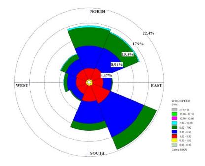
FIGURE 2. WAVE AND CURRENT DATA PRESENTATION: WIND ROSE (BLOWING TO)
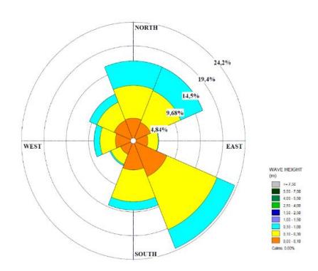
FIGURE 3. WAVE AND CURRENT DATA PRESENTATION: WIND ROSE
The design of the floating dock involves the utilization of conventional plastic drums interconnected to wooden frames by ropes. The decking of the dock employs wooden planks that have been coated with fiber oil and oil paint coating. This floating dock structure serves the dual purpose of facilitating berthing and loading/unloading operations, serving as an extension of the existing jetty structure. During the design phase of the floating dock, various alternative size configurations were considered, with the chosen dimensions based on the intended capacity of the passenger ships that will utilize the dock. Typically, the vessels (as depicted in Figure 3) employed in this area for passenger and cargo transport are simply accommodating 15-18 passengers per trip, with an estimated passenger weight of 80 kilograms per person. Accordingly, it was determined that the floating dock would need to accommodate passenger loads ranging from approximately 1.2 to 1.6 tons per vessel trip. In light of these requirements, the requisite area for the floating dock was established at 20 square meters. Subsequently, a sensitivity analysis of several floating dock layouts was conducted, involving a comparison of material usage and the assessment of structural static stability [7]. For the sake of conciseness, the specific layout selection process is not
elaborated upon in this paper, but isometric and 2D views of the floating dock are provided in Figures 4 and 5, respectively.
FIGURE 4. SMALL PASSENGER VESSEL USED AT THE LOCATION
FIGURE 5. FLOATING DOCK MODEL ISOMETRIC VIEW
a. Top View
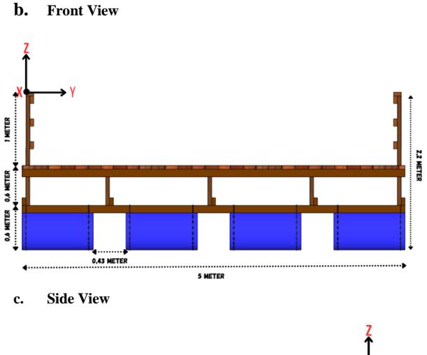
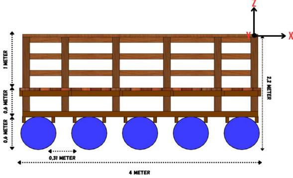
FIGURE 6. FLOATING DOCK MODEL 2D VIEW
The structural design of the floating dock incorporates wooden stake piles (refer to Figure 6(a)) to provide resistance against lateral and transverse movements of the floating dock. In the vertical heave direction (Z direction), the dock is designed to adapt to varying water surface conditions, encompassing high tide, low tide, and even extreme wave conditions. A dynamic stability analysis of the floating pier specifically focused on the heave direction. The analysis employed the wave equation based on diffraction theory, accounting for additional mass and damping effects experienced by the dock structure. It was determined that the response amplitude of the floating dock structure reached 1.08 meters, resulting in an increased full draft of the floating dock structure to 1.57 meters. Subsequently, an assessment of the structural response was conducted across different frequency variations, represented as the Response Amplitude Operator (RAO) [8]. The response amplitude of the floating dock was found to be 1.08 meters per meter of wave amplitude at a wave frequency of 1.38 radians per second. Given the significant deformation observed in the floating dock structure, it is advisable to refrain from operating the pier structure during conditions of extreme wave activity.
The calculation of the loads on wooden piles is initially simplified by defining the loads acting on the entire system. Essentially, the wooden pile structure encounters two types of loads: the environmental load exerted directly on the piles themselves and an additional load arising from the need to counter longitudinal and transverse deformations induced by waves and currents affecting the floating dock. The determination of wave and current loads affecting the pier structure is carried out through the application of basic principles of mechanics. The free body diagram depicting these forces is presented in Figure 6(b). The calculated values for these loads are as follows: the transverse wave load (FGT) amounts to 25.39 kN/m, the longitudinal wave load (FAL) equals 25.39 kN/m, the transverse current load (FAT) registers at 0.053 kN/m, and the longitudinal current load (FAL) is recorded as 0.02 kN/m. A straightforward mechanics analysis considering uniform wave and current loads yields resistance values: RT values of 25.342 kN for each pole and RL values of 31.714 kN for each wooden pile.
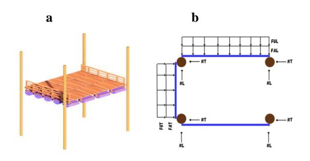
FIGURE 7. FLOATING DOCK WOODEN PILING: (a) FLOATING DOCK AND PILING ISOMETRIC VIEW; (b) LOAD DISTRIBUTION TO WOODEN PILE
III. COMMUNITY-BASED FLOATING DOCK CONSTRUCTION
The bill of quantity for the construction of the floating dock, as detailed in Table 1, outlines the essential materials required for this innovative project. The list includes 16 wooden piles, 25 plastic drums, 30 units of local Broti wood measuring 4 feet by 5 feet by 16 inches, 15 units of local Broti wood sized at 2 feet by 4 feet by 16 inches, and 40 wooden planks measuring 2 feet by 6 feet by 16 inches. Additionally, the bill comprises 20 sets of threaded bolts, 200 sets of bolts and nuts, 10 packs of 8mm thick rope, and 5 kilograms of 3-inch White Iron nails, along with 15 kilograms of 4-inch White Iron nails. For finishing and protective purposes, the bill includes 6 kilograms of fiber oil and 6 kilograms of oil paint. These quantities are meticulously calculated to ensure the successful construction of the floating dock, aligning with the project's design and structural requirements.
TABLE 1. BILL OF QUANTITY FOR A FLOATING DOCK
| No | Description | Unit | Quantity |
|---|---|---|---|
| 1 | Wooden pile | Unit | 16 |
| 2 | Plastic drum | Unit | 25 |
| 3 | Local Broti wood 4 ft x 5 ft x 16 inch | Unit | 30 |
| 4 | Local Broti wood 2 ft x 4 ft x 16 inch | Unit | 15 |
| 5 | Wooden plank 2 ft x 6 ft x 16 inch | Unit | 40 |
| 6 | Threaded bolt | Set | 20 |
| 7 | Bolt and nut | Set | 200 |
| 8 | Rope of 8 mm | Pack | 10 |
| 9 | Nail 3 inch White Iron | kg | 5 |
| 10 | Nail 4 inch White Iron | kg | 15 |
| 11 | Fiber oil | kg | 6 |
| 12 | Oil Paint | kg | 6 |
Figure 7 provides a detailed illustration of the meticulous construction process for the wooden frames that comprise the floating dock's integral structure. This building technique involves the deft combination of locally sourced Broti wood beams, renowned for their strength and durability, with threaded bolts and nuts. As they form the foundational framework for the entire floating dock, the assembly of these components requires precision. The interplay of these materials, as well as the secure fastening achieved through the use of bolts and nuts, ensures the frame's capacity to connect all the beams into a unified wooden structure.
FIGURE 8. CONSTRUCTION OF WOODEN FRAMES FOR FLOATING DOCK
Once the wooden frames have been constructed, the subsequent phase of the construction process unfolds seamlessly. This pivotal step involves the installation of plastic drums positioned strategically beneath the wooden frames, a procedure that forms the core of the dock's buoyancy mechanism. The secure attachment of these drums to the wooden frames is accomplished through the strategic use of ropes (see Figure 8). This interconnected framework of wooden frames and buoyant plastic drums constitutes the fundamental structure of the floating dock, imparting it with the essential buoyancy required to remain afloat on the water's surface.
FIGURE 9. INSTALLATION OF PLASTIC DRUMS FOR FLOATING DOCK
Upon the successful installation of the wooden frame structure and the integrated plastic drums, a crucial final step in the construction process ensues: the meticulous painting of the entire wooden frame structure, as shown in Figure 9. This vital protective measure involves applying both fiber oil and oil paint as a shield against the corrosive effects of seawater. By applying a protective coating to wooden structures, this method not only improves their durability, but also significantly increases their longevity. This protective layer of paint is akin to an armour, protecting the wooden components from the unrelenting challenges posed by the marine environment, such as the corrosive effects of saltwater, thereby ensuring the floating dock's durability and functionality.
FIGURE 10. PAINTING THE WOODED FRAME STRUCTURE
After the floating dock has been painted, the next step in the construction process is to relocate the finished structure, as illustrated in Figure 10. The floating dock is carefully towed from its construction site ashore to a position adjacent to the existing jetty. This crucial manoeuvre positions the floating dock in its designated location. This relocation is a crucial step in the development of the project, paving the way for the floating dock to fulfil its intended function of facilitating berthing, loading, and unloading operations.
FIGURE 11. PULLING THE FLOATING DOCK TO INSTALLED LOCATION
FIGURE 12. INSTALLATION WOODEN PILES AROUND THE FLOATING DOCK
Following the successful relocation of the painted floating dock to its designated position near the existing jetty, the subsequent phase of the construction process focuses on enhancing its stability and resilience. This critical step involves the installation of wooden piles, a key structural element, with a particular arrangement in mind. To bolster the floating dock's stability against environmental forces, the installation strategy entails combining three wooden piles for each set, strategically positioned at the four edges of the dock. This configuration serves as the cornerstone of the dock's structural integrity, fortifying it against the ship berthing load and dynamic forces exerted by the marine environment, including current and waves. The installation of these wooden piles is a meticulous undertaking that requires the expertise of local divers who play a pivotal role in this process. With precision and skill, these divers assist in securely placing the piles onto the seabed, ensuring that they are firmly anchored and provide the necessary support to maintain the floating dock's stability. This collaborative effort involving divers, craftsmen, and engineers underscores the multifaceted nature of the construction project.
IV. CONCLUSION
The design and construction of the community-based floating dock on Parit Island, Indonesia, exemplifies a remarkable blend of innovation, community engagement, and sustainability. This project addresses the critical need for inter-island transportation and docking infrastructure, especially in small islands such as Parit Island. The project's success can be attributed to its careful consideration of local metocean conditions and extensive stakeholder input, which demonstrates a commitment to both community needs and environmental stewardship. Sustainability and community empowerment are highlighted by the use of eco-friendly materials and local labor. This project embodies the convergence of traditional craftsmanship and modern engineering, from wooden frame assembly to plastic drum installation and protective painting. Stability is increased in a dynamic marine environment through the placement of wooden piles by local divers. This initiative not only improves the lives of Parit Island's residents, but also serves as a model for sustainable infrastructure development in island-rich regions with similar characteristics. It demonstrates the transformative potential of communitydriven projects that prioritize community engagement and environmental stewardship, thereby serving as a source of inspiration for future endeavors.
ACKNOWLEDGEMENT
The project to design floating dock in Parit Island was funded by the ITB Community Service project for the 2023 fiscal year, through the Center for Rural Areas Development-ITB.
REFERENCES
- [1] Sutton-Grier, A. E., Wowk, K., & Bamford, H. (2015). Future of our coasts: The potential for natural and hybrid infrastructure to enhance the resilience of our coastal communities, economies and ecosystems. Environmental Science & Policy, 51, 137-148.
- [2] Muller, A., Guinee, J., & Heijungs, R. (2017). Environmental and socio-economic approaches to the allocation of costs and benefits in life cycle impact assessment. Journal of Cleaner Production, 140, 942-953.
- [3] Ohl, C., Arnold, A., Uys, H., & Andrade, M. (2020). Floating Shipyard Design: Concept and Application. In WCFS2019: Proceedings of the World Conference on Floating Solutions (pp. 67-80). Springer Singapore.
- [4] Mahadkar, S., Mills, G., & Price, A. D. (2012). Stakeholder consultation practices within healthcare infrastructure planning: A conceptual approach to strategic asset management. Built Environment Project and Asset Management, 2(2), 127-145.
- [5] Martin, L., & Perry, F. (2019). Sustainable construction technology adoption. In Sustainable construction technologies
- (pp. 299-316). Butterworth-Heinemann.
- [6] Ministry of Transportation. (2013) Peraturan Menteri Perhubungan Nomor 17 Tahun 2013 tentang Rencana Induk Pelabuhan Tanjung Balai Karimun (in Bahasa Indonesia), Indonesia.
- [7] White, F. M. (2016). Fluid Mechanics. New York: McGraw-Hill Education.
- [8] Chakrabarti, S. L. (2005). Handbook of Offshore Engineering. Illinois: Elsevier.